Beam There, Done That
So, you’re using VoidSafe®… Now you can incorporate VoidBeam™
Our VoidSafe® Protection System (VS) is specifically designed to cover service holes effectively, significantly reducing risks related to both workers and equipment falling from height.
Although it’s possible to cut holes in the VoidSafe® panels to allow for individual service pipes or ducts within a riser, the size, spacing and positioning of any such holes must be carefully considered.
The details below highlight some of the issues that might occur when forming holes in Glass Reinforced Plastic (GRP) grating.
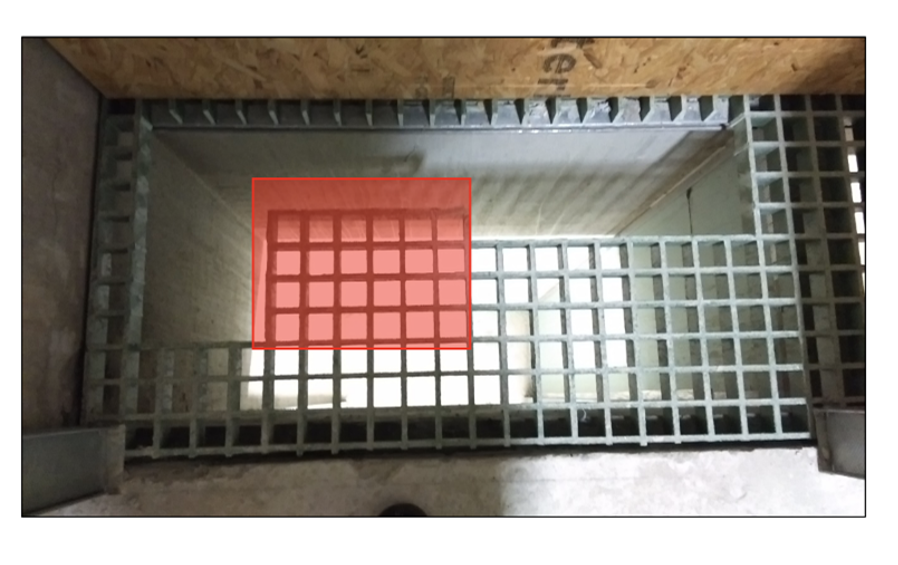
Figure 1
Figure 1 shows an example of a large L shaped section of the GRP panel which has been removed, leaving a point of weakness in the form of an unsupported corner in the centre of the panel.
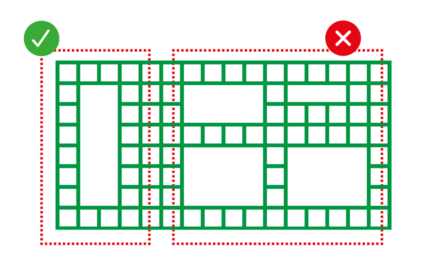
Figure 2
Figure 2 represents the shape of a GRP panel that is to be cut in-situ to fit around services within a riser on one of our contracts (the panel will be supported on all four sides). In this situation, the GRP panel will need to be cut correctly to allow access for one single pipe to the left of the panel (ticked), leaving a sufficient self-supporting area. On the right of the GRP panel, however, the GRP panel needs to be cut away so much that it is useless and could easily break under foot traffic.
To avoid these dangerous situations, important rules for cutting VoidSafe® panels have been developed.
A line of multiple openings must not be set out perpendicular to the short span of the VoidSafe® panels. Figure 3 shows what is acceptable and unacceptable for multiple holes in a row.
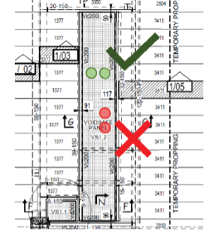
Figure 3
In addition to this, the minimum distance between holes in the panels must be 300mm and the minimum distance between a hole and an unsupported edge must also be 300mm. This dimension is equivalent to 7 bars of VS38.
The maximum hole size without a requirement for additional support is 200mm – equivalent to 5 bars of VS38. Figure 4 clarifies these dimensions.
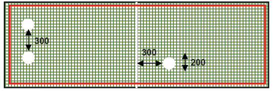
Figure 4
The above rules for void location and spacing are based on VoidSafe® panel load limits of 0.75kN/m² Uniformly Distributed Load (UDL) or a point load of 1.5kN (maintenance access – BS EN 1991-1-1) and are typically governed by deflection. A deflection of span/200 or span/130 is often used but the deflection limits applied depend on the application. The above rules do not take deflection limits into account.
Sometimes, however, service pipes and ducts will be set out in such a way that it’s not possible to follow these rules. In these cases, additional support for the VoidSafe® will be required.
Introducing VoidBEAM™
VoidBEAM™ provides increased strength using 110mm x 80mm steel trimmer supports placed on top of the VoidSafe™ panels before any holes are formed, or where excessive loadings are required on the GRP panel.
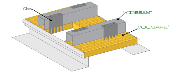
Figure 5
The steel claws bolted to the VoidBEAM™ frame (Figure 5 and 6) are designed to pass through the grid (hung below) and support the GRP panel from above, providing the ability to withstand up to 2.5kN UDL and 1.5kN of concentrated loads. The galvanised mild steel beams effectively act as trimmers to any openings in VoidSafe® panels and can be used across up to 3m in width. It is essential that they are installed prior to the formation of any openings.
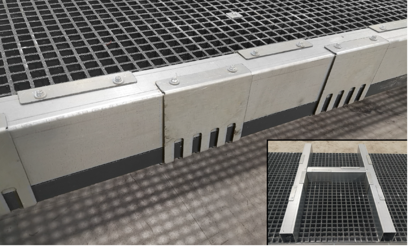
Figure 6
The beams are easy to install and fix and they also act as an up-stand protection around openings by defining the void edges.
Please refer to the VoidBEAM™ Product Data Sheet for full product specification. SMD offers a full design, supply and installation service, either independently or as part of our floor deck package. Contact our Sales team for more information on estimating@smdltd.co.uk.


