The quantity, or spacing, of shear studs on a composite steel beam is specified by the steel designer and shown on the steelwork general arrangement drawing. This can be as a note against each individual beam, a general note on the drawing or a combination of the two. Where SMD are contracted to produce the decking layouts, the information supplied by the steel designer will be incorporated into a shear stud label applied to each beam.
Sometimes the steel frame may be designed with beams running at an angle across the deck span. These are known as raking beams and it’s important to consider the impact this has on the shear stud design. The distance between the centres of the deck troughs along the centre line of any raking beam is greater than that for a beam perpendicular to the deck span due to the angle between the deck and the steel. This directly affects both the number and the achievable spacing of any studs. The TR+ profiles are most affected by this issue as they have wider ribs than R51+ which results in the loss of stud position flexibility.
Some steel frame design software packages only consider the stud numbers required for the composite design in terms of the beam length and deck trough centres, without considering any angled orientation or whether it is indeed practical to weld the number of studs required onto the raking beam. This important design consideration is demonstrated below. For these examples, it is assumed the SMD TR60+ profile with shear studs at 333mm (or one per trough) has been specified.
Studs along beams perpendicular to deck span
The studs as specified match the TR60+ trough spacing. If eleven studs are required for the design, they would be detailed as “11-333” on the decking layout.
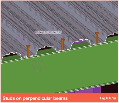
The number of studs required in this situation is calculated simply by dividing the beam length by 333. Single studs are shown in Figure 6.6.1a.
Stud distance along the raking beams as specified – not achievable
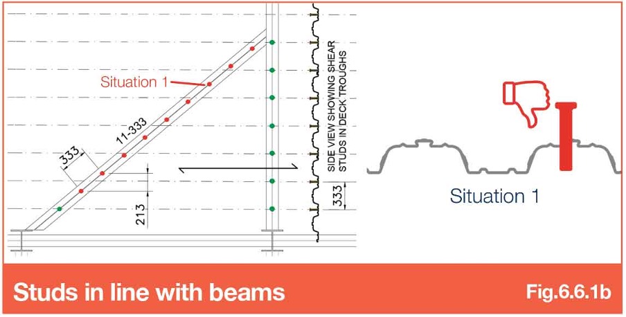
Figure 6.6.1b shows two beams in plan – one perpendicular, and one at an angle, to the deck span. The dash-dot lines represent the centres of the deck troughs and therefore where the shear studs must be located on the beams.
Stud installation at 333mm centres along the perpendicular beam on the right is achievable. Placement of the eleven required studs at 333mm centres on the centreline of the beam on the left (raking beam), however, is not possible. Due to the angle of the beam, the studs effectively fall at 213mm centres perpendicular to the deck span which does not match the troughs of the deck profile. The diagram shows the studs as red dots where they cannot be installed as they fall in a location covered by a rib shown in situation 1.
Studs installed along raking beams (placed in the deck troughs) – achievable
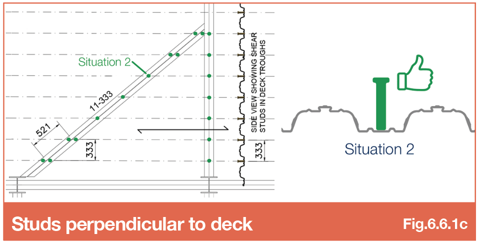
Placing shear studs on the raking beam in the deck troughs would result in single studs actually being located 521mm apart along the beam centre-line.
If it is essential to achieve the quantity of studs specified on the beam (eleven) and the beam flanges are wide enough, studs can be installed in pairs at each end of the beam to achieve the correct number as shown in Figure 6.6.1c. This arrangement needs to be proposed as early as possible in the design stage and must be checked by the steel designer as each stud in a pair provides a lower resistance than a single stud. The total number of studs on the beam may need to be increased for this configuration.
Alternatively, the deck can be cut along raking beams with very wide flanges to leave a gap in which the studs can be placed at the intended centre to centre spacings. Closure flashings will need to be detailed either side as necessary to ensure full bearing for the deck.
In summary
- In composite beam design it’s important to carefully consider any beams that are neither perpendicular, nor parallel, to the deck span. As discussed, the angle of these beams will influence both the number and spacing of the shear studs.
- When specifying shear studs on raking beams, particular attention should be paid to the width of the top flange. A narrow top flange may prevent doubling up of studs to try and achieve the required number. Where the beam has a particularly wide top flange there is an option to separate the deck along the centreline of beam with the use of closure flashings so that studs can be installed easily at the specified spacings.
Further Guidance
For more information on this topic and other shear stud spacing situations, refer to Section 6.6 – Shear stud spacing on TGN Online.
TGN Online
Register your details to gain access to our Technical Guidance Notes (TGN) Wiki pages. Alternatively, complete the form below and we’ll send you a hard copy of our TGN Manual.


