
Technical Guidance Notes
11.10 - VoidSafe® Protection System
VoidSafe® Protection System is a product that has been developed by SMD for use with metal decking and edge trim.
VoidSafe® is a moulded non-slip composite Glass Reinforced Plastic (GRP) floor grating system, it is designed, supplied and installed by SMD along with the metal deck operations.
The installation of VoidSafe® eliminates the requirement for void handrail protection systems and temporary void protection during construction, providing a final void riser protection product which minimises floor obstructions during the process.
Material specification
Two main components produce composite GRP: Polyester, resin and glass fibres. Isopthalic polyester resin is used to manufacture VoidSafe® mesh due to its flexibility and cost.
Fire resistance
- Standard Iso Resin - BS 476 Part 7 Class 2
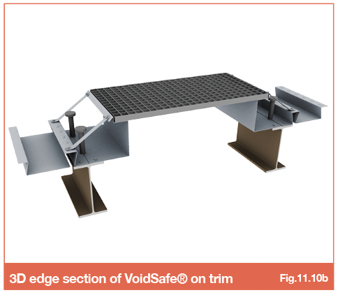
Typical edge detail
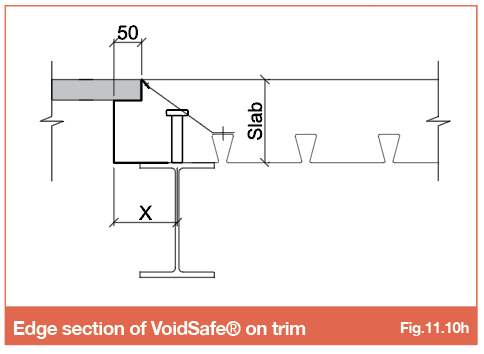
The minimum bearing required for VoidSafe ® is 50mm. Around the void perimeter, the VoidSafe® is supported on specially engineered trim manufactured from 2.0mm gauge material with a 40mm recess to provide the VoidSafe® at the same level as the adjacent slab.
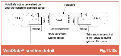
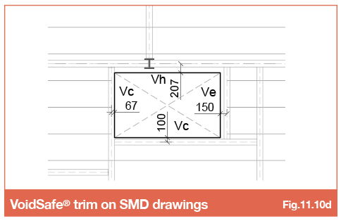
Slab edge dimensions should be read in the same way as normal slab edge dimensions on drawings. VoidSafe® trim is marked on drawings with a ‘V’ prefix as shown below.
VoidSafe® edge trim corners should be formed in such a way as to offer sufficient support for the VoidSafe® and also ensure the VoidSafe® is not cast in to the concrete slab when poured.
Edge Trim design and limitations
The acceptable overhang for VoidSafe® (VS) trim differs from that of standard edge trim. This is due to the additional load applied by the VS panel and any construction load applied to it, in addition to the wet concrete. Therefore, the acceptable overhang is governed not only by the slab depth, but also the span of the VS panel.
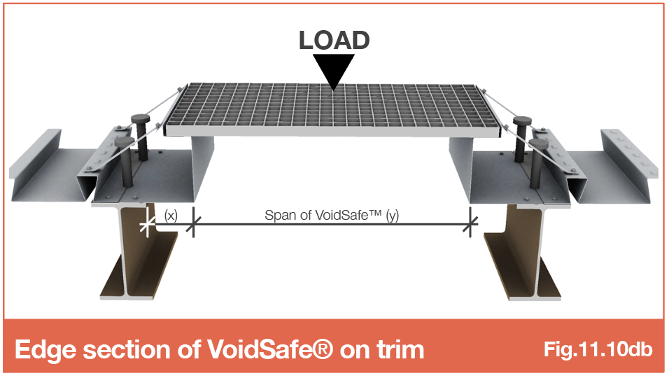
Where VS trim is specified, the following graph must be referenced for the maximum acceptable overhang (x):
.png)
The above graph is based on the following assumptions as standard practice for VS trim:
- A maximum of 1.0kN/m² (100kg) is applied to the VS panel during construction – in accordance with BS EN 1991-1-6 table 4.1.
- 2.0mm gauge edge trim
- Maximum 250mm slab depth
- Standard fixings to the trim @ max. 250mm centres or enhanced Hilti X-ENP @ max. 500mm centres In locations where the overhang exceeds that shown in the table contact SMD Technical Team for further guidance.
VoidSafe® trim supported on cantilevered deck
Where it is necessary to cantilever the deck to achieve a large edge dimension (shown in section below) and still support the VoidSafe® panels, this is only achievable along the short edge of the void (shown ticked in Fig.11.10.dd) as the fixing between deck and trim becomes the critical aspect during construction stage (pre-concreting). The long edge of the void should always have the trim fixed directly to the edge beam (in accordance with the rules outlined above) as this is the primary support for the VoidSafe® panel covering the void during the construction stage.
If cantilevering the deck is unavoidable along the long edge of the void then temporary propping will be required to the deck to provide appropriate support to the edge trim, or walking on the VoidSafe® must be prohibited until the concrete has been cast.
.png)
.png)
.png)
.png)
.png)
Fig. 11.10de-1 - Support for VoidSafe SMD can install back to back edge trim at the perimeter beam which will form a strip of concrete in the final condition to support the VoidSafe. However, this must be wide enough to allow access for the shot fired fixing gun to fix these edge trims to the beam. If concrete at the perimeter beams is not an option, then structural steel supports would be required (by others). SMD edge trims are only designed as a temporary support and concrete shuttering, they are not a permanent structural support, so cannot be used in the final condition.
Fig. 11.10de-2 - Structural Angle welded to posts, welded to top of beam (by others). Min 55mm bearing for VoidSafe panel. GRP Panel fixed to RSA.
Fig. 11.10de-3 - Box Section welded to top of beam (by others). GRP Panel fixed to box beam.
Design considerations for the installation of shear studs with VoidSafe®
When designing voids and composite beams with the intention to use VoidSafe®, ensure consideration is given to the installation of shear studs on perimeter void beams as the studs can clash with the trim, depending on the size of the beams being used. Refer to Section 6.6 - Shear stud spacing, Section 6.6.2 Studs on beams with VoidSafe ® edge trim for more information.
Pre-cut to size
VoidSafe® is delivered to site pre-cut to fit the void. There may be a requirement for some site cutting down, or notching required during the installation process, however this should be minimal. Should the mesh require trimming or cut on site, the correct PPE must be used. Face fitted mask with minimum P3 particle filter.
The pre-cut VoidSafe® GRP sheets are individually labelled to correspond to the SMD drawing, giving the level and phase location for each sheet.
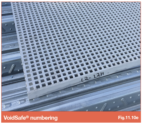
Materials off loaded on site
As with all other SMD materials, vertical distribution should be carried out by others, with horizontal distribution by SMD. The weight table located in the VoidSafe® RAMS should be consulted prior to lifting the grating sheets.
Installation on site
Thought must be given to others working around you. While VoidSafe® produces an amount of dust if cut on site, the dust created is non-toxic. Consult the COSHH data sheet prior to commencement of cutting VoidSafe®.
VoidSafe® system should be installed while the safety nets are in place below the voids being protected. There will generally be no need for handrail, or edge protection panels, where VoidSafe® grating is to be installed. However, in instances where handrails are in place, it should be removed to allow clear access for VoidSafe® grating installation.
Once each VoidSafe® grating sheet has been securely fixed in to position, the safety nets can then be de-rigged in preparation for stud welding works to follow.
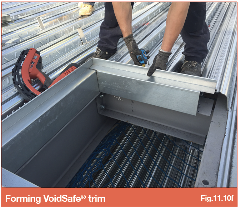
Forming VoidSafe® trim
Each side of the void will need to be formed separately, with attention for overlapping of trim sections to form a neat "shelf" for the GRP mesh to be seated on.
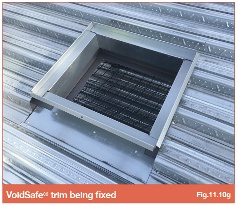
Fixing VoidSafe® trim
Edge trim must be fixed in the usual way using suitable fixings, with restraint strap installed at the centres detailed on the drawing.
Bearing requirements for VoidSafe® GRP panels.
There must be a minimum bearing point of 50mm on the shortest span of the VoidSafe®.
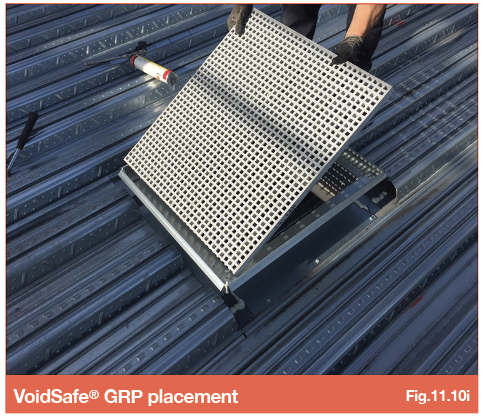
The VoidSafe® grating should be placed in to position using the fixing types noted below.
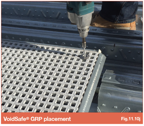
Fixing of VoidSafe / GRP Panels
VoidSafe/GRP panels require a minimum of 50mm bearing onto structural supports to at least two sides in the final condition.
Fixing the VoidSafe/GRP panels down to the supports
Different fixings can be used to fix the GRP/VS panels to the material below at end and side supports. Top fixings should be a minimum of 4 fixings and washers per sheet, one in each corner, fixed at maximum of 1000mm centres
- VSX – Screw and washer
- VS19 – Screw and washer
- VS38 - Screw and washer or M-Clip with bolt M6 40mm Socket Cap.
- VS50 - Screw and washer or M-Clip with bolt M6 35mm Socket Cap.
Fixing types for VoidSafe/GRP panels into various materials
Consideration must be given to the material that the VoidSafe/GRP panel is being fixed to.
- Fixing into edge trim/light gauge steel - 5.5mm x 85mm Hex Head Tek Screws with washer.
- Fixing into hot rolled steel - S-MD05S Self Drilling Metal Screws (or similar) 5mm x 65mm with washer - steel may need to be pre-drilled.
- Fixing into to concrete/blockwork - Hilti HPS-1 Impact Anchor (or similar) 6mm x 80mm with washer - concrete will need to be pre drilled.
- Fixing to other materials - In other situations, a GRP panel may be fixed to materials to cover voids or to provide a walkway. If fixed into any other type of material, use the appropriate fixing type.
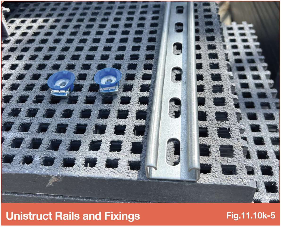
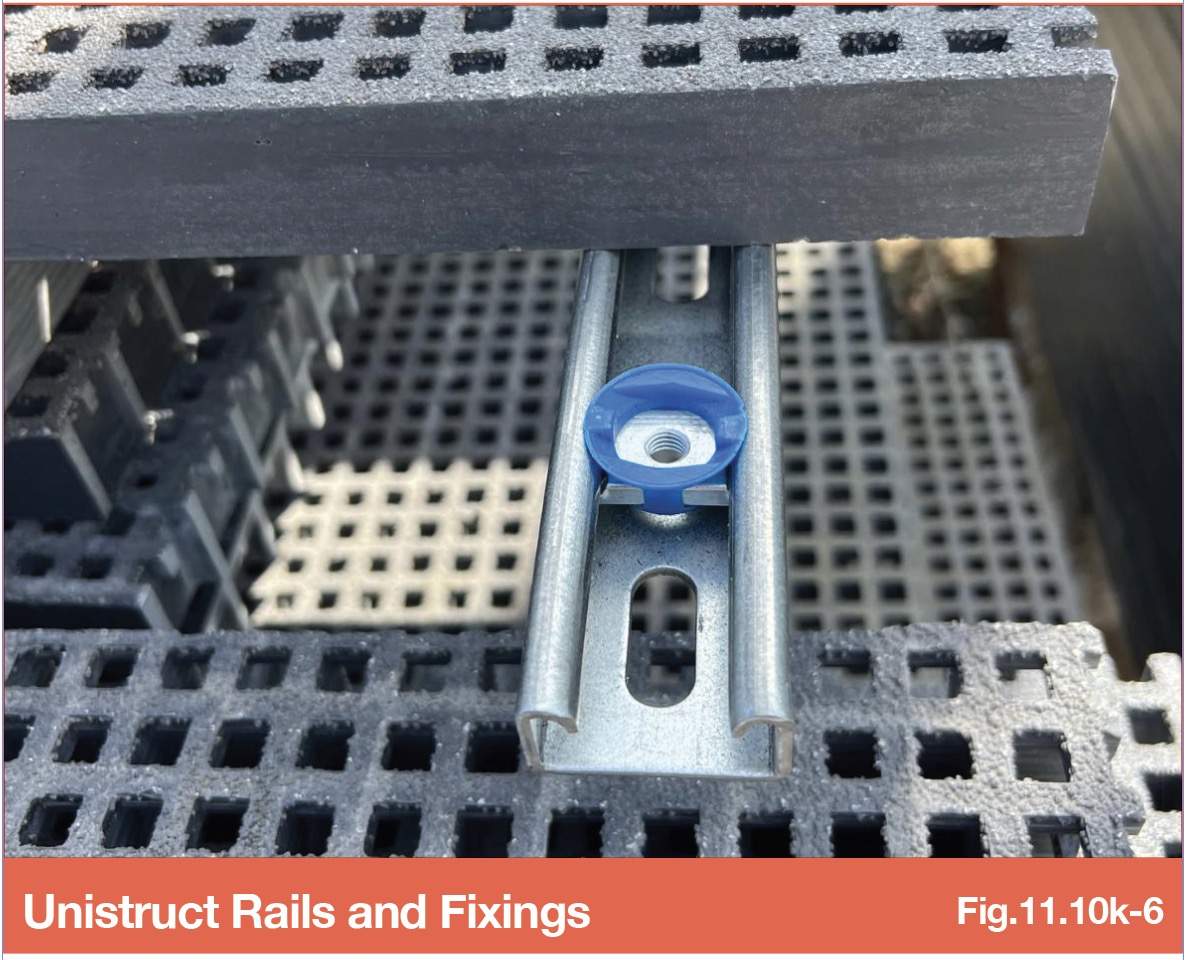
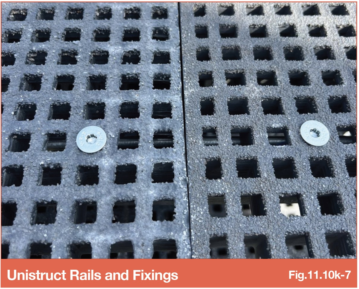
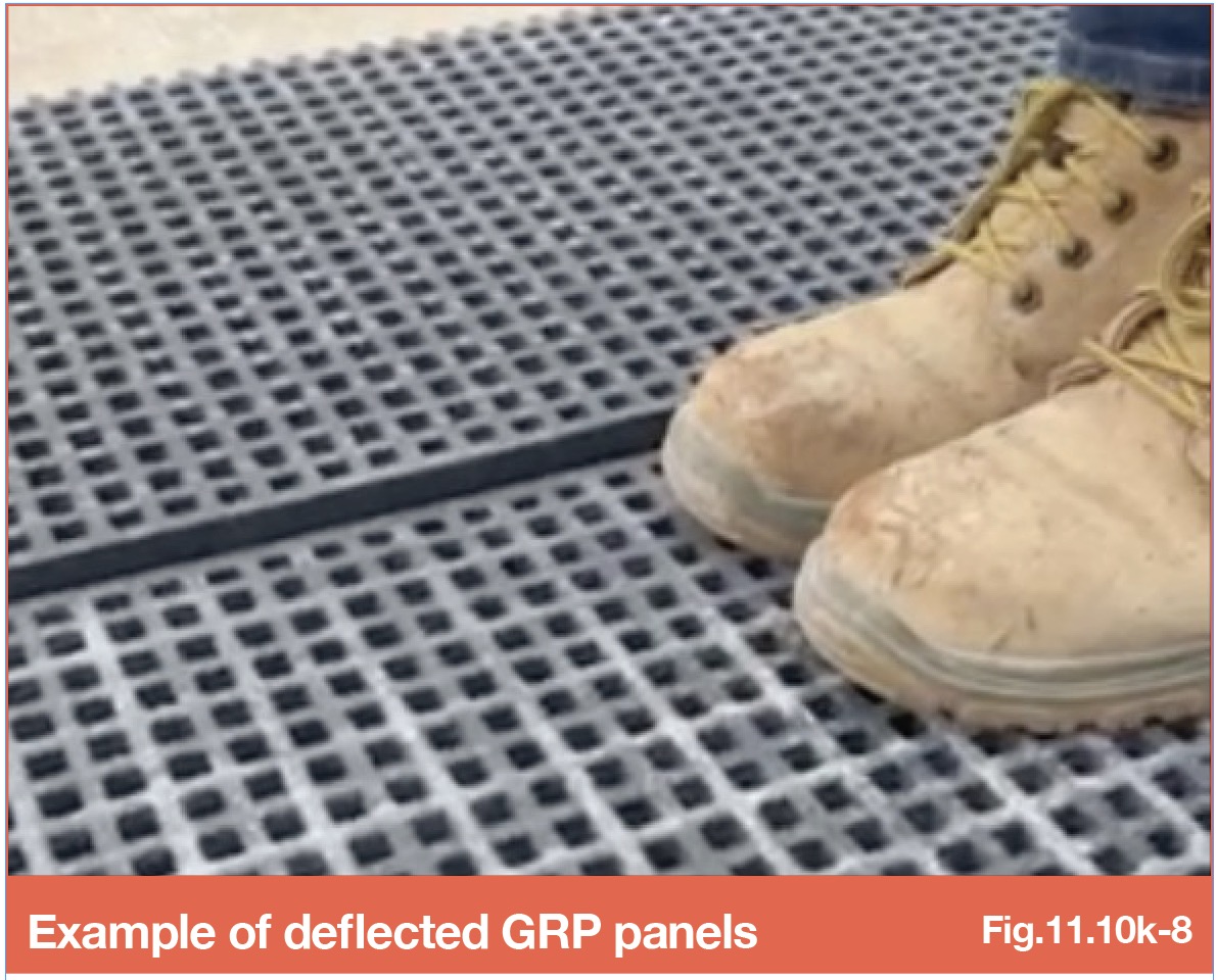
Side Fixings - (Fig.11.10k-5 to Fig.11.10k-8)
When fixing VoidSafe,it is essential that the fixing specification is followed. These items are supplied by SMD
- VSX - Unistrut galvanised channel with screw and clamp nut fixing). 300mm 41 x 21 x 2.5mm Slotted Channel / Strut. This option will require holes drilled to the top surface to install the support.
- VS19 (mini-mesh) - Unistrut galvanised channel with screw and clamp nut fixing. 300mm 41 x 21 x 2.5mm Slotted Channel / Strut.
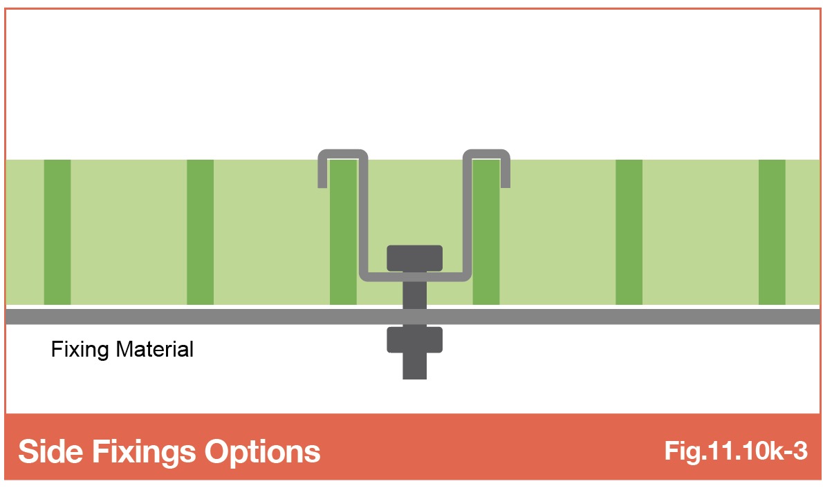
- VS38 - C-Clip (381 x 25w x 45d) with bolt M6 50mm Socket Cap, screw and washer
- VS50 - C-Clip (421 x 25w x 55d) with bolt M6 50mm Socket Cap, screw and washer
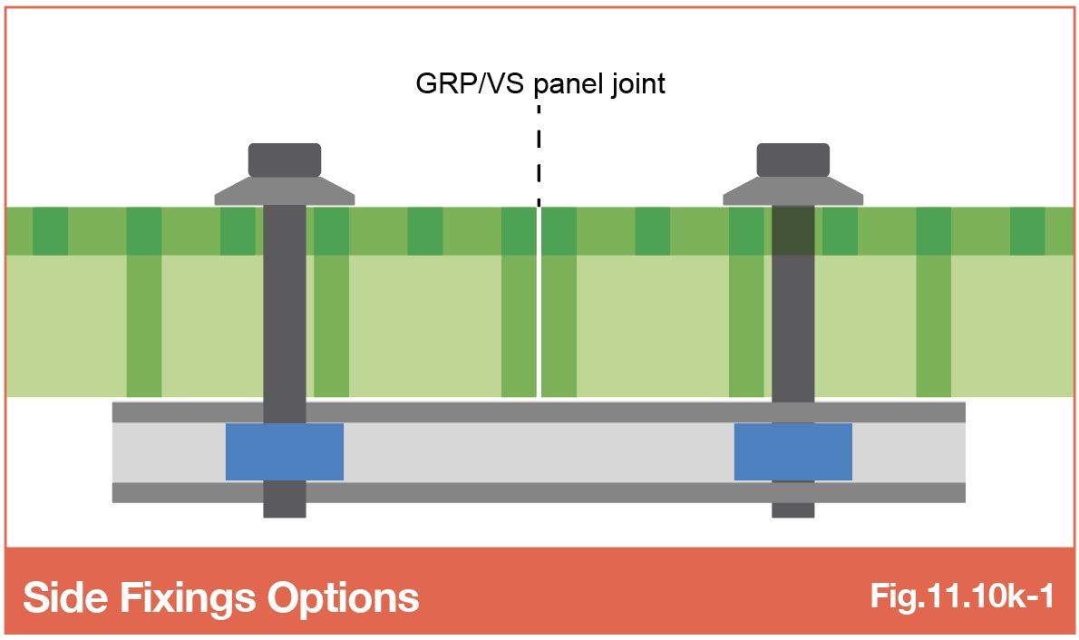
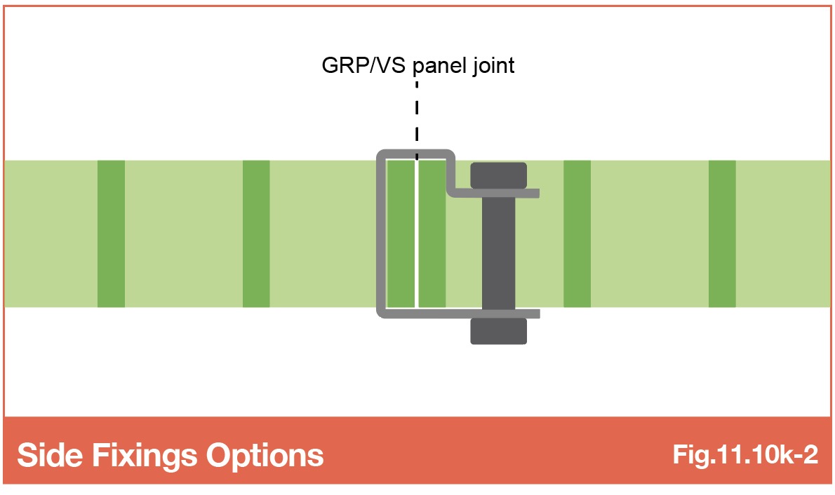
When installing two or more VoidSafe/GRP panels together - (Fig.11.10k-1to Fig.11.10k-4)
Where two or more GRP panels butt against one another, in certain situations the GRP panels should be fixed together to avoid each panel moving independently at the joint, potentially causing a trip hazard.
Rules to fix Voidsafe(VS)/GRP panels together;
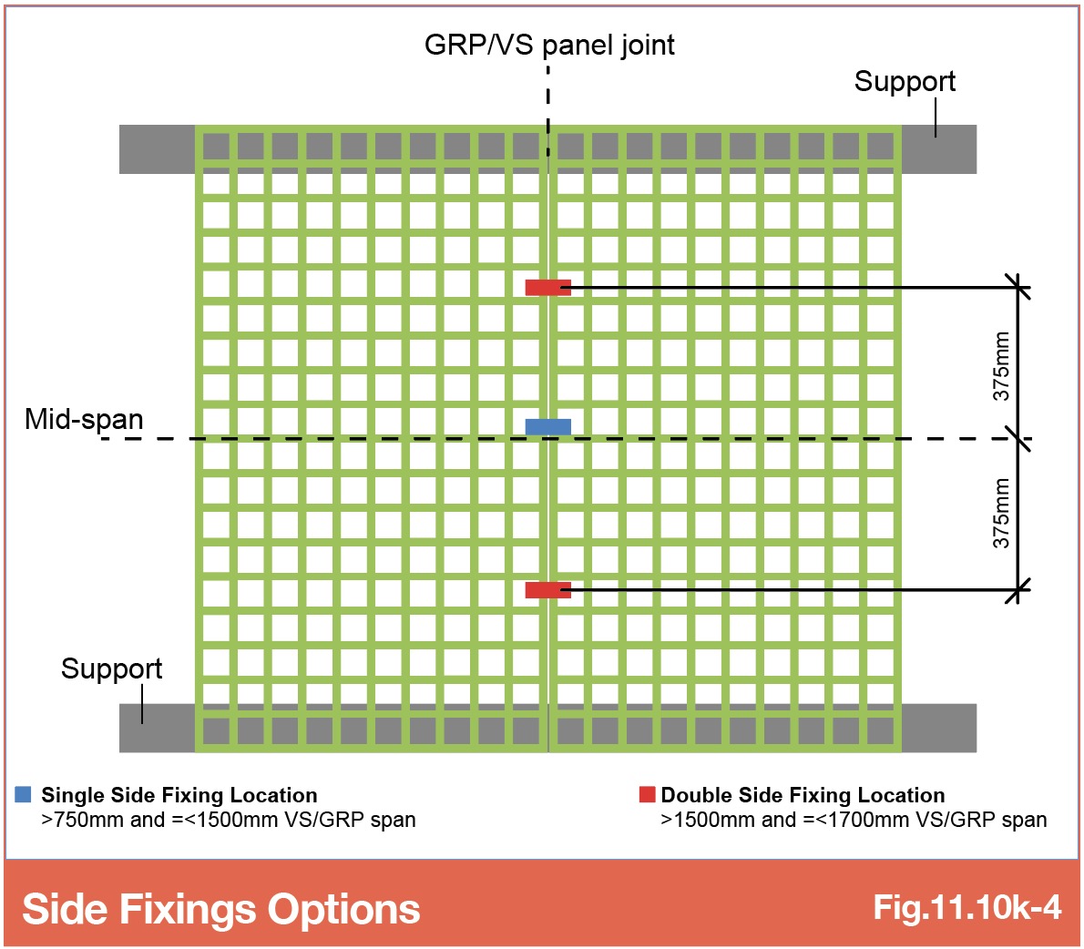
- =<750mm VS/GRP span - no side joint fixing is required as deflection is not excessive under foot traffic.
-
750mm and =<1500mm VS/GRP span - a single side joint fixing is required between panels located in the centre of the span.
-
1500mm and =<1700mm VS/GRP span – Two side joint fixings are required, located 750mm apart centred about mid-span (375mm either side of mid-span).
- VS panels must not be used greater than a clear 1700mm span. Alternative void protection should be used.
Fixing considerations for installation when fixed to hardened concrete.
Consideration must be given to the material that the GRP panel is being fixed to. If used with the VoidSafe Protection System, the GRP panel would normally be fixed directly onto the bespoke metal edge trim. If however, should the GRP panel is to be installed after the concrete slab has been poured, a different type of fixing should be used as metal screws cannot drill into the hardened concrete slab which encases the metal edge trim. In other situations, a GRP panel may be fixed to materials to cover voids or to provide a walkway.
Service hole forming
Only holes that have been identified, designed and approved on SMD drawings can be cut out on site by SMD. It is the responsibility of others to check the support requirements and structural properties of the VoidSafe® grating sheet in the event of further holes and cut-outs being required.
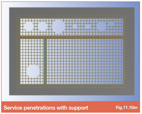
Where service penetrations are required in the VoidSafe® GRP mesh, additional trimming support may be required. Should holes be required, a detailed hole layout must be submitted to enable any additional support requirements to be specified.
This information should be made available at design stage, to avoid the need for support to be installed retrospectively.
Rules for forming service holes in VoidSafe® GRP panels
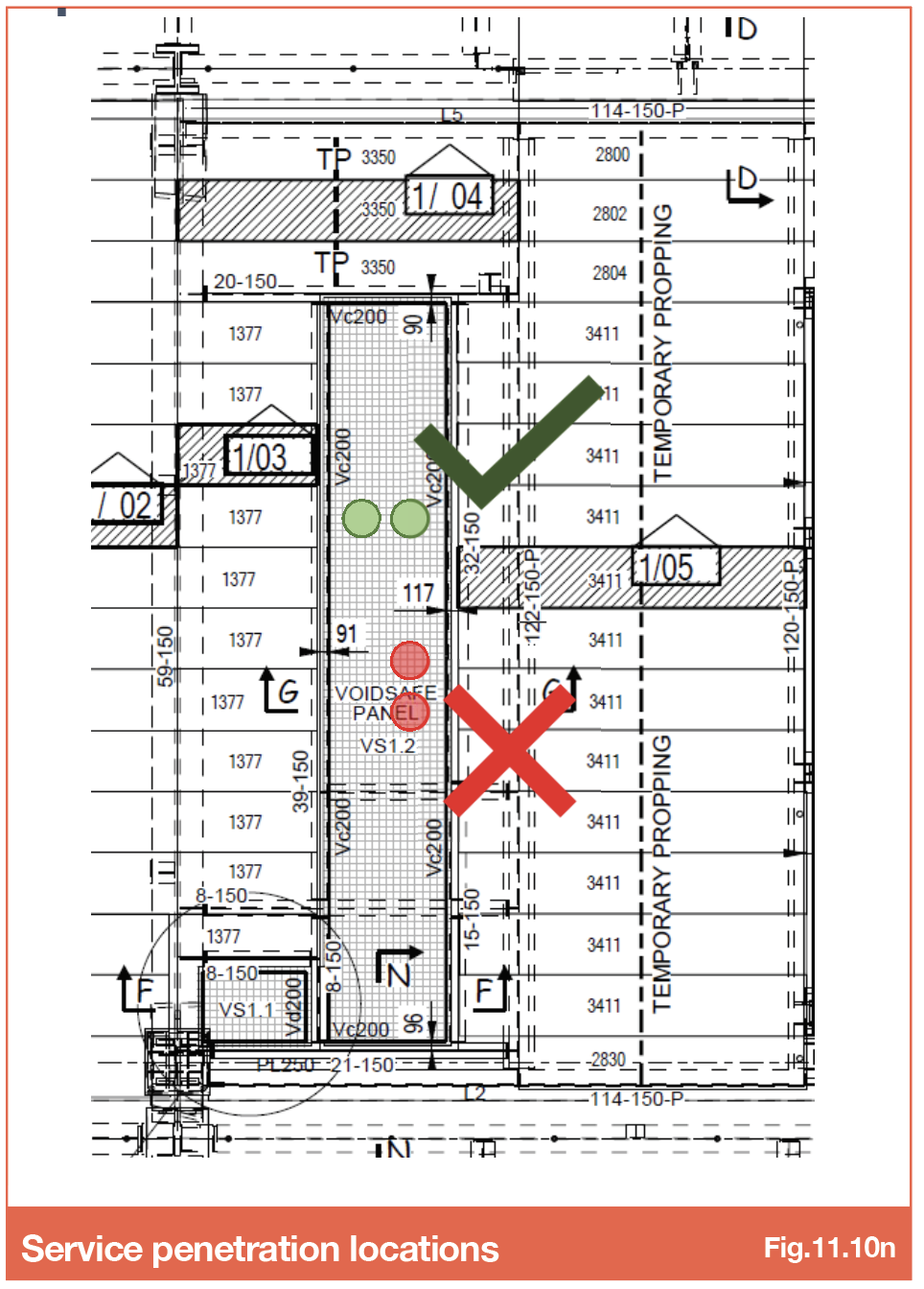
- When positioning voids in a line, chose positions that do not cut across the short span of the VoidSafe® panels (refer Fig.11.10o).
- The minimum amount of grating left between holes is 300mm (7 bars of VS38).
- The minimum amount of grating between a void and an unsupported edge must be 300mm (7 bars of VS38 - refer Fig.11.10o).
- The maximum void size without possible requirement for support is 200mm (5 bars of VS38 - refer Fig.11.10n).
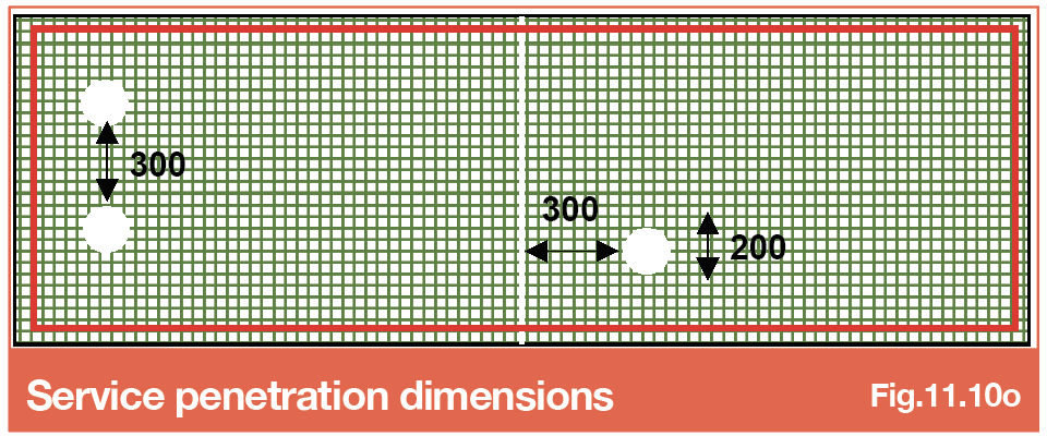
Where it is necessary to go outside of these rules, additional support is likely to be required.
Criteria that affects hole position: VoidSafe® panel load limits are typically governed by deflection so these differ depending on the application and deflection limit applied (span/200 or span/130 are often used). The above rules do not consider deflection limits.
Loading
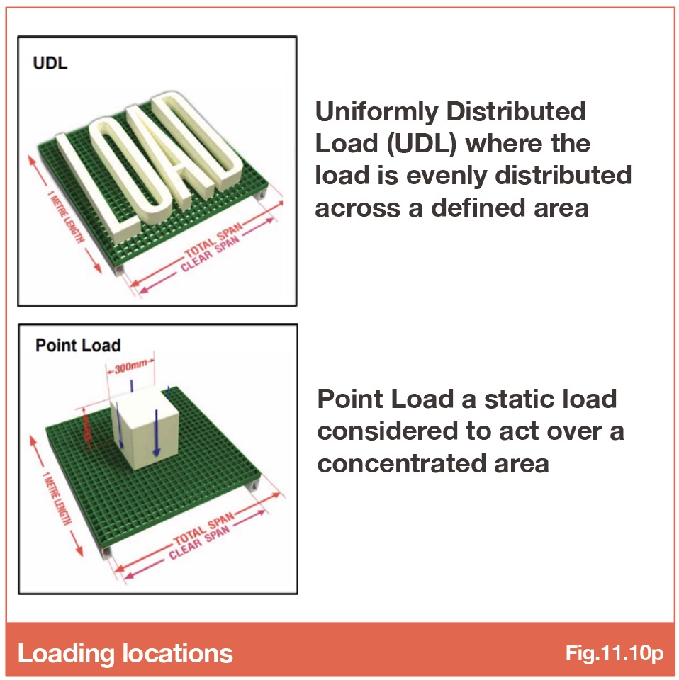
As with all typical designs, there are two types of loading to consider: The ‘rules of thumb’ are based on 0.75kN/m² UDL or point load of 1.5kN – for maintenance access from BS EN 1991-1-1.
Voids that fall outside of the above rules
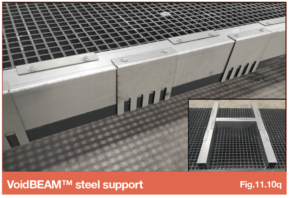
The VoidBEAM™ product is available for use with VoidSafe® Protection System. VoidBEAM™ provides increased strength using 110mm x 80mm steel trimmer supports placed on top of VoidSafe™ panels before holes are cut in the GRP or where excessive loadings are required on the GRP panel.
Using steel claws bolted to the VoidBEAM™ steel frame, the GRP panel is supported from above providing increased strength up to 2.5kN UDL and 1.5kN concentrated loads. See VoidBEAM™ Product page on SMD website for full product specification.
Keywords - void voids opening openings hole holes box out former
.png)





Structural Metal Decks Limited
The Outlook, Ling Road, Poole, BH12 4PY
Registered in England & Wales No. 03560591
Tel: +44 (0) 1202 718898
SMD® 2025