6.6 - Shear stud spacing
In accordance with BS EN 1994-1-1 or BS5950-3 Section 3.1:1990+A1 2010, the dimensions and configurations shown in Figs 6.6a to 6.6f must be followed to ensure the welded shear studs are effective to provide the documented stud resistance values.
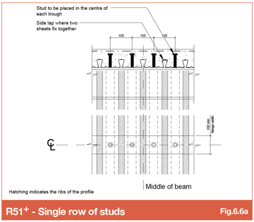
Refer SMD Detail Sheet SMD.DOD.185 - R51 Single studs
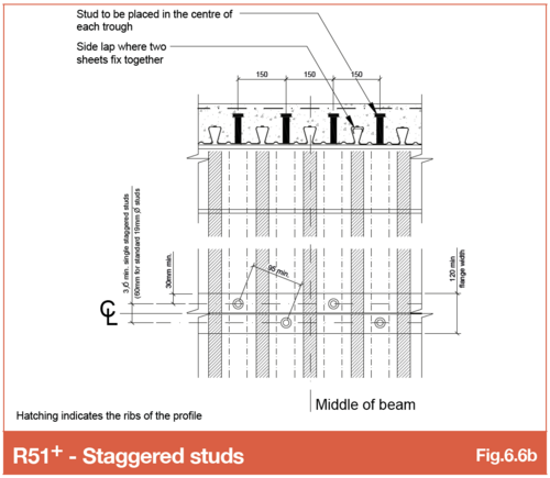
Refer SMD Detail Sheet SMD.DOD.183 - R51 Staggered studs
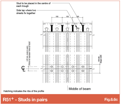
Refer SMD Detail Sheet SMD.DOD.184 - R51 Studs in pairs
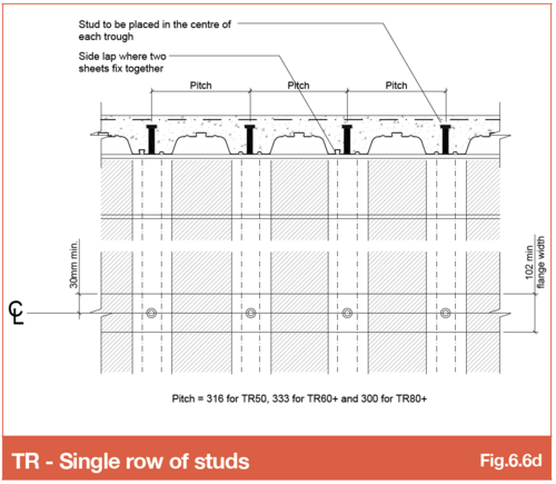
Refer SMD Detail Sheet SMD.DOD.182 - TR+ Single studs
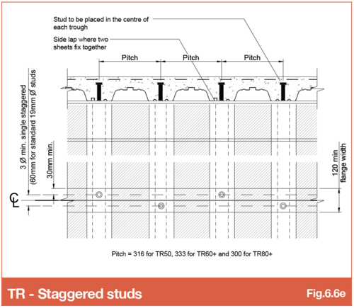
Refer SMD Detail Sheet SMD.DOD.180 - TR+ Staggered studs
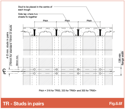
Refer SMD Detail Sheet SMD.DOD.181 - TR+ Studs in pairs
6.6.1 Studs to raking beams
The quantity or spacing of shear studs required on composite steel beams are specified by the steel designer. This is typically the structural engineer with the quantity or spacing of studs indicated as a note against each individual beam on the steel general arrangement drawing. SMD, where contracted, add shear stud labels to the deck general arrangement drawings using the information specified by the steel designer.
It is important where steel beams are raking across the deck span to consider the impact this has on stud numbers or spacings achievable due to the increase in the distance between troughs caused by the angle of the rake. Some steel frame design software packages only consider stud numbers in relation to beam length and requirement for the composite beam design without considering a raking deck orientation or whether it is possible to get the studs onto the beam where the deck is raking. Detailed below are examples where this issue needs consideration.
Studs at 333mm centres to beam perpendicular to deck span
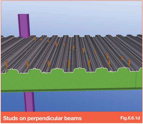
SMD TR60+ profile has deck troughs at 333mm, meaning where deck is perpendicular to the beam CL, studs must be detailed at 333mm. The quantity of studs achievable in this situation is essentially beam length divided by 333. This can be increased by detailing pairs per trough if the beam width permits
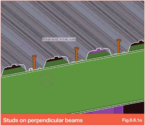
Studs at 333mm centres along the raking beam
The dotted centre lines show the location of the deck troughs and therefore where the shear studs must be located on the beam.
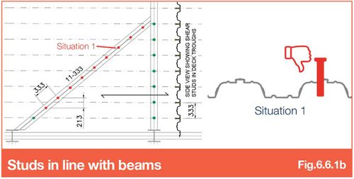
Trying to instal 11 studs at 333mm centres in line with the angle of the beam is not possible (studs shown red where they cannot be installed).
In the example shown and due to the angle of the beam, the studs effectively fall at 213mm centres perpendicular to span which is not in the deck troughs and, hence, not achievable.
Studs at 333mm centres perpendicular to the deck (not the beam)
Placing shear studs on the centre line of the deck troughs and in line with the raking beams, means the studs are actually located 521mm apart (and not 333mm due to the angle of the beam).
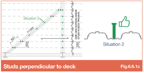
If it is essential to achieve the quantity of studs on the beam, and the beam flanges are wide enough, studs in pairs can be installed at each end of the beam to achieve the correct number of studs. This will need to be checked by the steel beam designer as each stud in a pair provides a lower resistance than a single stud. Therefore, the number may need to be increased for this configuration.
Stud number and spacing considerations
Consideration should be made when specifying the shear stud quantity/spacing on a steel frame that has beams that are raking to deck span.
In summary, it is important to consider raking beams and influence on number/spacings when specifying shear studs on beams that are not perpendicular or parallel to the deck span. Particular attention should be made on raking beams with narrow top flanges as it may be impossible to double up studs (in pairs) due to the flange width. Where beams are wider it may be possible to separate the deck along the CL of beam with closure flashings to enable studs to be installed - contact SMD Technical team for further guidance.
6.6.2 Studs on beams with VoidSafe ® edge trim
If you intend to specify the use of VS on your contract it’s important to consider the implications as early as possible in the design stage.
The GRP floor grating panels are supported on bespoke edge trim that differs from the normal slab edge containment system. The top section of this trim is formed into a recess in which the panels are seated, allowing them to be flush with the top of the slab.
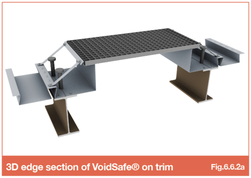
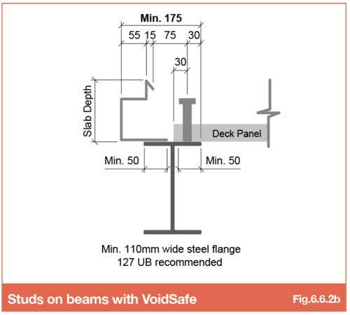
As a result, there are certain minimum dimensional requirements for void slab edge locations in relation to the beam flange edges and the shear studs (Fig.6.6.2b).
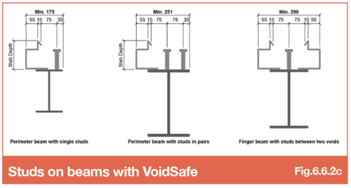
The presence of the recess also has an impact on the minimum beam size that can be used. The details in Fig 6.6.2c show three typical situations on studded beams, along with the permissible dimensions between the slab edge and the inner toe of the flange. They also show minimum distances to the studs from the back of the edge trim and from the toe of the flange.
The minimum dimension of 175mm from the void edge to the inner flange toe for a beam with single studs is increased to 251mm when pairs of studs are required and 290mm where double trim is necessary on a single beam (ie a ‘finger’ beam between two separate voids).
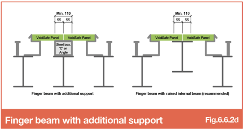
Alternative solutions for installing VoidSafe® on finger beams are to either introduce a steel packer or raise the beam to the soffit of the panels as shown in Fig 6.6.2d. There is a minimum width for this intermediate support as well.
Planning ahead is time well spent. In the example below (Fig 6.6.2e), the slab edges coincide with the edges of the steel trimmers. The specified beams are only 102mm in width and as a result the backs of the 55mm wide trim recesses overlap the deck sheets that are bearing 50mm onto the other side of the trimmers. There is certainly no room for shear studs.
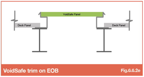
This shows clearly how the logistics of the installation of VS must be taken into account when specifying the beam sizes, shear stud requirements and slab edge locations. It is not possible to stud weld through both deck and trim – this rule also applies to normal edge trims. No attempt should be made to insert edge trims of any sort under previously installed deck sheets.
The earlier that the proposed service riser details are shared, the easier it is to make changes to steel sizes or edge locations if this sort of clash is detected. Once the beams have been fabricated and/or delivered to site the issue becomes difficult and expensive to resolve.
What size trimmers?
The minimum width for the void trimmers should be 150-165mm. This is to ensure that the deck and edge trim can be fixed separately with no overlap, especially when the slab edge is at the toe of the flange.
Go to NEXT section

