

Difference between revisions of "13.3 - VoidSafe™ Protection System"
| Line 9: | Line 9: | ||
| − | Refer to '''[https://smdltd.co.uk/ | + | Refer to '''[https://smdltd.co.uk/service-and-products-brochure/ Services and Products Brochure]''' for span data for all our GRP products. |
Revision as of 08:37, 2 July 2021
VoidSafe ™ is a moulded non-slip composite Glass Reinforced Plastic (GRP) floor grating system, it is designed, supplied and installed by SMD along with the metal deck operations.
The installation of VoidSafe™ eliminates the requirement for void handrail protection systems and temporary void protection during construction, providing a final void riser protection product which minimises floor obstructions during the process.
Material specification
Two main components produce composite GRP: Polyester, resin and glass fibres. Isophthalic polyester resin is used to manufacture VoidSafe ™ mesh due to its flexibility and cost.
Refer to Services and Products Brochure for span data for all our GRP products.
Fire resistance
- Standard Iso Resin - BS 476 Part 7 Class 2
Typical edge detail
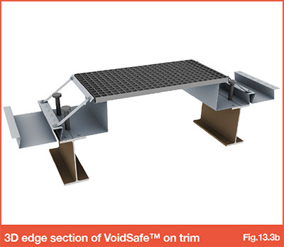
The minimum bearing required for VoidSafe™ is 50mm. Around the void perimeter, the VoidSafe™ is supported on specially engineered trim manufactured from 2.0mm gauge material with a 40mm recess to provide the VoidSafe™ at the same level as the adjacent slab. Ref Fig 13.3a and 13.3b.
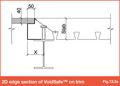
X = 114mm minimum, this will need increasing for shallow slab depths (<150mm).
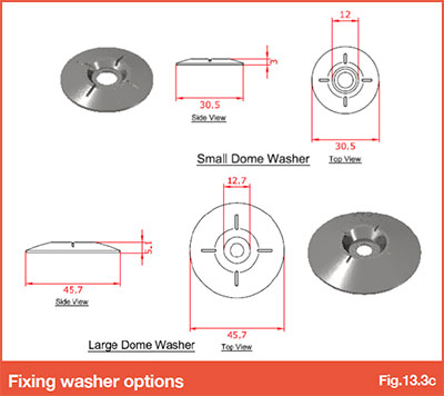
Fixings
Fixings must be in each corner, be at a minimum of 1000mm centres and there should be a minimum of 4 fixings in each sheet.
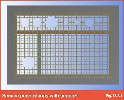
Service penetrations
Where service penetrations are required in the VoidSafe™ Protection System, additional trimming support may be required. Should voids be required, a detailed void layout must be submitted to enable any additional support requirements to be specified.
This information should be made available at design stage, to avoid the need for support to be installed retrospectively.
Go to NEXT section