

4.1 - Benefits of composite metal deck
- Rapid speed of construction, reducing overall project time
- Provides the tensile reinforcement requirements of the slab
- Composite Construction reduces steelwork frame weight
- Reduced foundation costs, due to reduced loading
- Integral ceiling and service fixing system
- The decking acts as permanent shuttering
- Provides a cover for following trades
- When fixed, the decking provides a safe working platform
- Minimal site storage requirements
- Easily installed into complex designs, with minimal wastage
- Can achieve up to 4hr fire rating for the slab
4.1.1 Construction stage
At Construction Stage the decking is designed to support the weight of the wet concrete, reinforcement and an allowance for temporary construction load in accordance with BS5950 Part 4 or BS EN 1991-1-6. Where this load is likely to be exceeded, SMD Technical Team should be consulted.
The best practice guidance for concrete placement outlined in this manual should be adopted to avoid overloading of the decking.
Where necessary to position materials directly on to the metal decking for short periods, the following recommendations should be followed:
- Any load applied to the metal decking during its temporary construction stage should be restricted to 1.5kN/m². Special attention is required when applying temporary loads where the deck requires propping during construction. Temporary propping must be in place, levelled and suitably braced before any construction traffic is allowed over the deck.
- Materials should always be positioned directly over suitable structural support.
- Materials should be positioned in a workmanlike manner.
- Materials should be placed onto timbers, pallets or similar, to spread any load. These should be positioned directly over structural support.
- Timbers or pallets should be positioned with the main support running perpendicular to the ribs of the decking.
NOTE: Metal decking is NOT designed to accommodate the storage of materials during its construction stage, therefore until the structural concrete topping is placed, any such storage undertaken is to be carried out with due regard to the above notes.
4.1.2 Construction stage deflection
Floor decks are designed to deflect under the weight of wet concrete as it is placed, in accordance with BS EN 1993-1-3 & BS EN 1994-1-1 or BS5950-4 & 6. Typically, decking is designed for the nominal slab thickness specified with no allowance for any additional load due to excessive concrete thickness as a consequence of deflection of the structural steel frame during construction.
Refer SMD Best Practice Data Sheet 10
In accordance with UK National Annex to BS EN 1994-1-1 and BS5950-4, the deflection of the deck at construction stage is limited to the lesser of Span/180 or 20mm, when the effects of ponding are not considered (deck deflection is less than slab depth/10). This limit is increased to the lesser of Span/130 or 30mm, when the effects of ponding are considered (deck deflection is greater than slab depth/10).
The above must be considered both in specification of the slab surface tolerance (by the designer) and when determining the concrete placement method to be adopted (by the main/concrete contractor).
4.1.2 Effect of construction stage deflection on surface and flatness tolerances
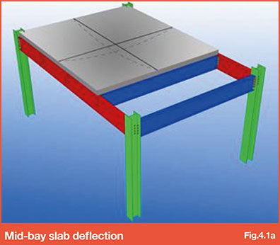
As recognised in BS 8204-2, SCI Publication P300 and Concrete Society TR75, it is not possible to construct concrete toppings on upper floor decks to a defined datum level due to deflections in both the deck and steel frame during construction. During concreting on metal deck, the supporting structure (deck, primary and secondary supporting steelwork) will deflect under the load from concrete and site operatives. This can occur for several hours following installation as the structure creeps under the weight of the concrete – Refer to Fig 4.1a for indication of how these deflections impact on the surface level/flatness achievable. This is compounded by the differing stiffness and deflections for different elements of the supporting structure due to beam sizes, spans, connections etc.
Rolling deflection will also occur during the concreting process (this subsequent ’Rolling’ deflection occurs in areas where concrete has already been placed as concrete placement progresses into adjacent deck sheets or structural bays). This is caused as a result of deflection of members connected to the area where concrete has already been placed. It is impractical to return to the initial area concreted to try and level the slab as any additional concrete will result in greater deflections and potential for overloading.
Due consideration must be given to this aspect by the Project Design Team when considering the effect this may have on following trades/finishes. For example, level to datum specifications are difficult to achieve unless steel beam spacing’s are reduced and tight deflection tolerances on supporting steelwork enforced. This design requirement will result in cost implications and therefore subsequent levelling screeds may be more appropriate to attain tight level to datum specifications.
Further guidance on recommended pouring methods and surface/flatness tolerance is available in Concrete Society TR75 and SCI AD344: Levelling Techniques for Composite Floors.
Go to NEXT section