

4.8 - Edge trim
Standard galvanised edge trim is provided where requested around perimeter and void edges. This edge trim acts as permanent formwork only to support the wet weight of concrete during construction.
Specialist edge trims for VoidSafe™ (refer Section 13.3 - VoidSafe™ Protection System) or with an integrated channel (refer section 13.5 - Channel edge trim) are also available.
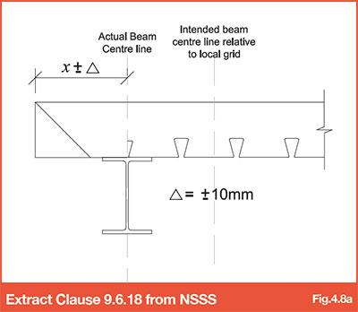
Depending on the structure of the design team for the contract, the edge dimensions will typically be provided by either the architect or structural engineer. In accordance with the National Structural Steelwork Specification (NSSS) the tolerance on trim position is +/-10mm from CL of beam, this is in addition to the acceptable tolerance for the perimeter steelwork.
Refer to National Structural Steelwork Specification (NSSS) 5th Edition for more information
In some instances tighter tolerances may be required to suit the cladding contractor. Where this is the case, positions for edge trim should be engineered on site by a site engineer either by advising dimensions from constructed steel position or marking a physical line for theoretical grid position on site to enable the edge trim to be installed accurately from this position and hence reducing the impact of perimeter steel tolerance on slab edge position. However, consideration should be given to the appropriate gauge of edge trim to accommodate this setting out.
Typically, edge trim is supplied to site in lengths of 3.0m where it is then cut to suit. Edge trims are available in varying gauges; 1.0mm, 1.2mm, 1.6mm and 2.0mm. The material gauge is determined by the depth of the concrete slab and the extent of the slab overhang (refer to Table 4.7c). Edge trim can be either fixed to the end of the decking with self-tapping screws (refer to Fig 4.7a) or to the main supporting structure, using similar fixings as that used to secure the decking (refer to Fig 4.7b).
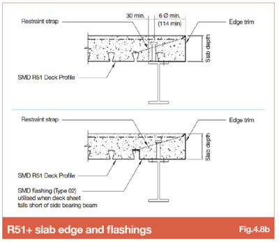
Refer to SMD Data sheet SMD.DOD.173 - R51 slab edge and flashings
The minimum bearings for edge trim are similar to that for the floor deck; 50mm on steelwork or 70mm for masonry or concrete supports. Edge trim should be fixed to supports at both ends and maximum 750mm centres along the length of the piece of edge trim, with restraint straps fixed between the top edge of the vertical leg and the floor deck at 750mm centres (typical), or 500mm centres for slab depths between 200-300mm.
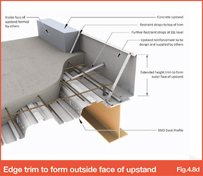
Where slab depth/edge trim height exceeds 300mm, two levels of restraint straps may be required alternated between the top edge of the vertical leg and mid-height (refer to Fig.4.8d).
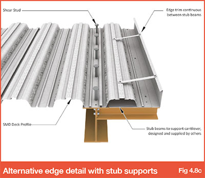
4.8.1 Alternative detail for large overhangs or cantilevers
Where slab edge overhangs or cantilevers exceed the limits mentioned above, typically temporary propping will be required to the edge prior to installation. This can cause practical or logistical issues on site. Alternatively, additional stub beams can be provided by the steelwork contractor. These large edges can then be formed using a sheet of deck running parallel to the perimeter beam, with trim stitched to the edge of the sheet (refer to Fig 4.8c), the stubs must be located at centres within the maximum un-propped span limits for the deck profile, gauge and slab depth combination.
4.8.2 Edge trim to form outer face of upstand
Typically, it is easier for the outer and inner faces of perimeter upstands to be formed traditionally.
Refer to SMD Data sheet SMD.DOD.166 - Trim Double restraint straps
In some instances where this is not practical, it is possible to provide extended height trim to form the outer face of the upstand (refer to Fig 4.8d). The internal face of the upstand will still require traditional formwork by others.
There are limitations on overall trim height and gauge, although where trim heights exceed 450mm high, additional bracing/propping to the vertical leg is likely to be required during construction, for further advice contact SMD Technical Department.
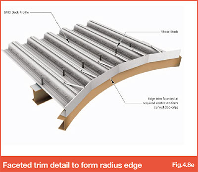
4.8.3 Curved / Faceted edges
Where edge trim is required to form a curve, straight lengths are provided to site and the edge trim cut to provide a faceted edge on site to form the desired radius (refer to Fig 4.8e).
The recommended tolerance for edge trim position from the desired radius is +/-25mm, this will be in addition to the perimeter steelwork tolerances at the location in question. During detailing the length of facets and spacing of set-out dimensions must be considered to ensure this tolerance can be achieved. Where tight tolerance control is required, physical dimensions for edge location should be engineered on site by a site engineer.
Go to NEXT section