Design Guidance – Using VoidSafe®
Helpful Early Design Considerations
What is VoidSafe® and why use it?
Health and Safety considerations are top of the list of priorities in the construction industry. Most buildings have a requirement for service risers to allow fixtures, cables, ducts and pipework to be easily installed and maintained throughout the lifetime of the building. The resulting voids in the floor slabs are a hazard, particularly during the construction phase, and SMD was the first UK decking company to design and develop a bespoke protection solution.
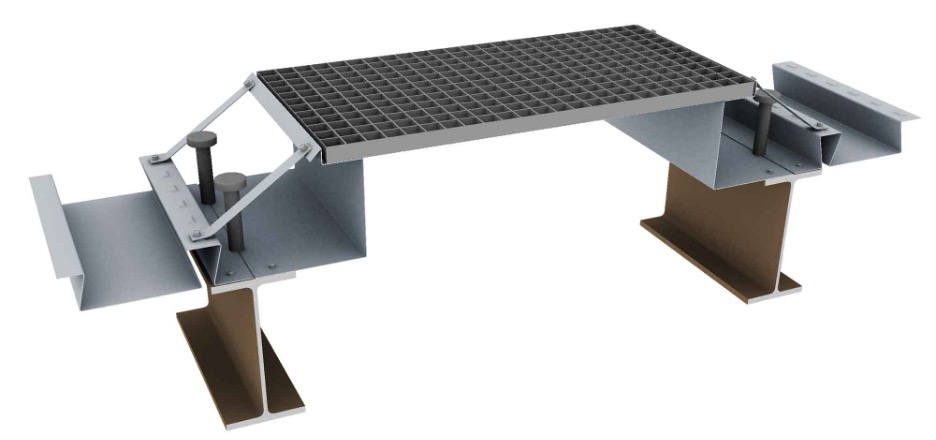
The VoidSafe® Protection System (VS) consists of non-slip composite Glass Reinforced Plastic (GRP) floor grating panels that cover small openings in the slab area and are installed by SMD as part of the metal deck operations. The system is durable, lightweight, chemical/corrosion resistant and can be left in place post construction, easily accommodating future individual service ducts.
The VoidSafe® Protection System (VS) consists of non-slip composite Glass Reinforced Plastic (GRP) floor grating panels that cover small openings in the slab area and are installed by SMD as part of the metal deck operations. The system is durable, lightweight, chemical/corrosion resistant and can be left in place post construction, easily accommodating future individual service ducts.
Cost effectiveness
The system contributes to overall site safety and improves site logistics during the construction stage whilst offering a permanent fixture that can be easily modified to suit the use of the riser or void that it protects.
Traditionally, contractors have provided hole protection in the form of handrails or scaffolding, but these solutions can actually become more expensive in terms of both time and cost, particularly when adaptions and re-configuration changes, as well as constant inspections throughout the programme are all factored in.
Use of VS means there is no need to move handrails time and time again for following trades, eliminating the requirement for further coordination and visits – and therefore cost – from a handrail supplier.
Design – It’s worth planning ahead
If you intend to specify the use of VS on your contract it’s important to consider the implications as early as possible in the design stage.
The GRP floor grating panels are supported on bespoke edge trim that differs from the normal slab edge containment system. The top section of this trim is formed into a recess in which the panels are seated, allowing them to be flush with the top of the slab.
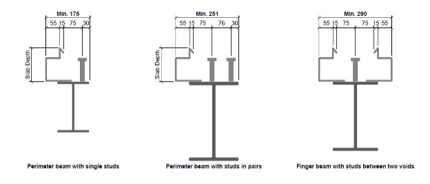
As a result, there are certain minimum dimensional requirements for void slab edge locations in relation to the beam flange edges and the shear studs. The presence of the recess also has an impact on the minimum beam size that can be used. The details in Figure 1 show three typical situations on studded beams, along with the permissible dimensions between the slab edge and the inner toe of the flange. They also show minimum distances to the studs from the back of the edge trim and from the toe of the flange.
The minimum dimension of 175mm from the void edge to the inner flange toe for a beam with single studs is increased to 251mm when pairs of studs are required and 290mm where double trim is necessary on a single beam (ie a ‘finger’ beam between two separate voids).
Figure 1
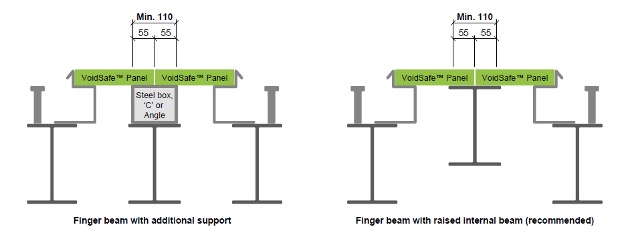
Alternative solutions for installing VoidSafe® on finger beams are to either introduce a steel packer or raise the beam to the soffit of the panels as shown in Figure 2. There is a minimum width for this intermediate support as well.
Figure 2
Planning ahead is time well spent. In the example below (Figure 3), the slab edges coincide with the edges of the steel trimmers. The specified beams are only 102mm in width and as a result the backs of the 55mm wide trim recesses overlap the deck sheets that are bearing 50mm onto the other side of the trimmers. There is certainly no room for shear studs.
Figure 3
This shows clearly how the logistics of the installation of VS must be taken into account when specifying the beam sizes, shear stud requirements and slab edge locations. It is not possible to stud weld through both deck and trim – this rule also applies to normal edge trims. No attempt should be made to insert edge trims of any sort under previously installed deck sheets.
The earlier that the proposed service riser details are shared, the easier it is to make changes to steel sizes or edge locations if this sort of clash is detected. Once the beams have been fabricated and/or delivered to site the issue becomes difficult and expensive to resolve.
What size trimmers?
The minimum width for the void trimmers should be 150-165mm. This is to ensure that the deck and edge trim can be fixed separately with no overlap, especially when the slab edge is at the toe of the flange.
Maximum overhang
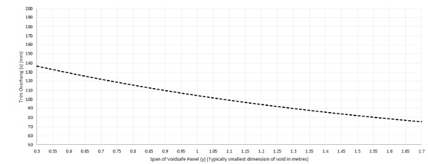
The acceptable overhang for VoidSafe® trim differs from that of standard edge trim, due to the additional load applied by the GRP panels and any construction load applied to them prior to the concrete curing. The permissible overhang is governed not only by the slab depth, but also the span of the VS panel and overhang of the VS trim.
Where VS trim is specified, you must refer to the graph provided in our Technical Guidance Sheet SMD-STA-1220 V4 (VoidSafe® Edge Trim design and limitations). This is reproduced below as Figure 4.
Figure 4
The graph is based on the following assumptions as standard practice for VS trim:
- A maximum of 1.0kN/m² (100kg) is applied to the VS panel during construction – in accordance with BS EN 1991-1-6 table 4.1.
- 0mm gauge edge trim is used.
- The maximum slab depth is 250mm.
- If standard fixings are used, they are applied at 250mm centres (max.) and if enhanced Hilti X-ENP fixings are used, they are applied at 500mm centres (max.).
In locations where the overhang exceeds that shown in the table, contact the SMD Technical Team for further guidance.
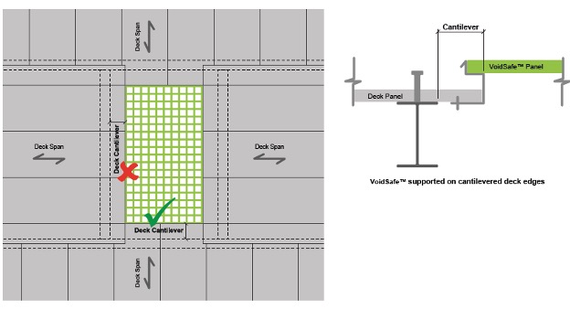
In some cases, it may be considered necessary to cantilever the deck to achieve a large edge dimension and still support the VS panels, as indicated in Figure 5 below. This is only achievable along the short edge of a void (the green tick on the plan view) as the fixing between deck and trim becomes the critical aspect during construction stage (pre-concreting). The long edge of the void should always have the trim fixed directly to the edge beam as this is the primary support for the VS panel during the construction stage.
If cantilevering the deck is unavoidable along the long edge of the void then temporary propping will be required to the deck to provide appropriate support to the edge trim. If this is not possible, walking on the VS panels must be prohibited until the concrete has been cast.
Figure 5
Should you have any trouble location any information, please let us know and we will direct you to the correct location.


