Difference between revisions of "4.4 - Lateral restraint and diaphragm action"
(Created page with "[https://smdltd.co.uk/technical-info/Contents '''Back to main Contents page'''] Metal deck may also be used as lateral restraint to stabilise the beams against lateral tors...") |
|||
| Line 11: | Line 11: | ||
'''Table 4.4a & 4.4b Safe Working Shear Resistances''' | '''Table 4.4a & 4.4b Safe Working Shear Resistances''' | ||
| + | |||
Figures for each profile are based on maximum fixing spacing over intermediate beams as mentioned in Section 4.6. | Figures for each profile are based on maximum fixing spacing over intermediate beams as mentioned in Section 4.6. | ||
[[File:4.4a.jpg|400px]] | [[File:4.4a.jpg|400px]] | ||
| + | |||
[[File:4.4b.jpg|400px]] | [[File:4.4b.jpg|400px]] | ||
| + | |||
[[File:4.4c.jpg|400px]] | [[File:4.4c.jpg|400px]] | ||
| Line 22: | Line 25: | ||
Refer to SCI Publication 093 and SCI Advisory Desk Note AD 175, BS EN 1993 or BS5950-9 for more information | Refer to SCI Publication 093 and SCI Advisory Desk Note AD 175, BS EN 1993 or BS5950-9 for more information | ||
| − | |||
| − | |||
| − | |||
Revision as of 13:46, 24 January 2017
Metal deck may also be used as lateral restraint to stabilise the beams against lateral torsional buckling during construction (where the deck spans perpendicular to the beam) and, through diaphragm action, to stabilise the building as a whole by transferring wind loads back to the walls or columns (where designed by the structural engineer).
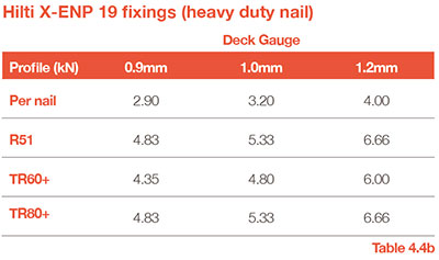
Deck is typically fixed to the beam flange using either powder (‘shot-fired’) or gas-actuated nails. Where fixings are required to resist lateral forces in accordance with BS EN 1993 or BS5950-1, the more robust Hilti X-ENP19 shot-fired nail (or similar approved) is recommended.
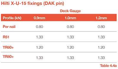
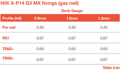
The safe working shear resistances (per nail) are indicated in the tables below– Note: In some instances the value differs depending on the decking gauge used.
Table 4.4a & 4.4b Safe Working Shear Resistances
Figures for each profile are based on maximum fixing spacing over intermediate beams as mentioned in Section 4.6.
Refer to SCI Publication 093 and SCI Advisory Desk Note AD 175, BS EN 1993 or BS5950-9 for more information
Other items within 4.0 - Design - Floor deck:-
[4.1 - Benefits of composite metal deck]
[4.2 - Sheet lengths]
[4.3 - Temporary propping]
[4.4 - Lateral restraint and diaphragm action]
[4.5 - Bearings / Support]
[4.6 - Fixings]
[4.7 - Cantilevers]
[4.8 - Edge trim]
[4.9 - Flashings]
[4.10 - Steps in slab]
[4.11 - End caps]


