

Difference between revisions of "4.5 - Bearings / Support"
| Line 1: | Line 1: | ||
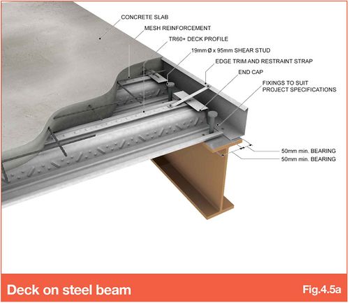
In accordance with BS5950 and Eurocode 4, the ends of all deck sheets require a minimum 50mm bearing onto a structural support (steel beam or angle). Adequate support should be designed/detailed by the steel frame designer (this may be the structural engineer or steelwork contractor depending on the contract specifics) and manufactured/installed by the steelwork contractor. | In accordance with BS5950 and Eurocode 4, the ends of all deck sheets require a minimum 50mm bearing onto a structural support (steel beam or angle). Adequate support should be designed/detailed by the steel frame designer (this may be the structural engineer or steelwork contractor depending on the contract specifics) and manufactured/installed by the steelwork contractor. | ||
| − | [[File:4.5a-V10.5.jpg| | + | |
| + | [[File:4.5a-V10.5.jpg|500px|link=]] | ||
| + | |||
When a 2D/3D CAD model is received, where possible, SMD will endeavour to highlight missing supports or additional requirements during the design/detailing process. However, please note the design, supply and installation of these supports is the responsibility of others. | When a 2D/3D CAD model is received, where possible, SMD will endeavour to highlight missing supports or additional requirements during the design/detailing process. However, please note the design, supply and installation of these supports is the responsibility of others. | ||
| Line 14: | Line 16: | ||
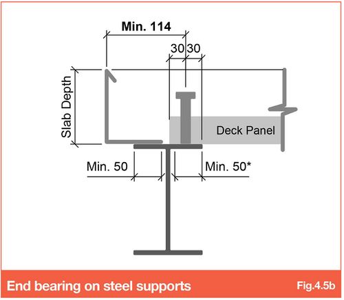
The minimum bearing requirements for deck and edge trim is 50mm* on steelwork (increased to 60mm where sheets are to receive thru-deck welded shear studs, (refer to Section '''[[6.0 - Design - Floor deck composite beam design]]''') and 70mm on masonry or concrete. | The minimum bearing requirements for deck and edge trim is 50mm* on steelwork (increased to 60mm where sheets are to receive thru-deck welded shear studs, (refer to Section '''[[6.0 - Design - Floor deck composite beam design]]''') and 70mm on masonry or concrete. | ||
| − | [[File:4.5b-V10.5.jpg| | + | |
| + | [[File:4.5b-V10.5.jpg|500px|link=]] | ||
| + | |||
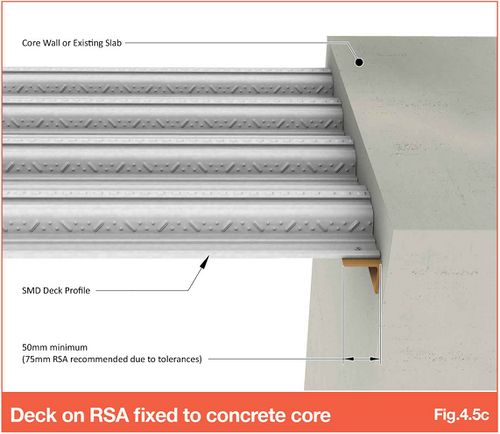
Where the deck is to butt up against a concrete core or similar, shelf angles are to be installed by others to provide adequate end bearing for the metal deck (Fig 4.5c). When developing such a detail, consideration must be given to the height of any continuity reinforcement extending from the core to ensure it does not clash with the troughs of the deck profile. | Where the deck is to butt up against a concrete core or similar, shelf angles are to be installed by others to provide adequate end bearing for the metal deck (Fig 4.5c). When developing such a detail, consideration must be given to the height of any continuity reinforcement extending from the core to ensure it does not clash with the troughs of the deck profile. | ||
| − | [[File:4.5c-V10.5.jpg| | + | [[File:4.5c-V10.5.jpg|500px|link=]] |
'''[https://smdltd.co.uk/wp-content/uploads/2017/01/23-RSA-Fixed-to-Core-Wall-CMYK.jpg Refer SMD Section Image 23]''' | '''[https://smdltd.co.uk/wp-content/uploads/2017/01/23-RSA-Fixed-to-Core-Wall-CMYK.jpg Refer SMD Section Image 23]''' | ||
| Line 26: | Line 30: | ||
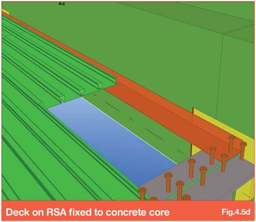
Where the deck runs parallel to a core wall (Fig.4.5d), an angle may not be necessary (SMD can provide a light gauge flashing in this instance). | Where the deck runs parallel to a core wall (Fig.4.5d), an angle may not be necessary (SMD can provide a light gauge flashing in this instance). | ||
| − | [[File:4.5d-V10.5.jpg| | + | [[File:4.5d-V10.5.jpg|500px|link=]] |
| Line 35: | Line 39: | ||
| − | [[File:4.5b.jpg| | + | [[File:4.5b.jpg|500px|link=]] |
| Line 44: | Line 48: | ||
| − | [[File:4.5c.png| | + | [[File:4.5c.png|500px|link=]] |
Revision as of 14:55, 23 March 2022
In accordance with BS5950 and Eurocode 4, the ends of all deck sheets require a minimum 50mm bearing onto a structural support (steel beam or angle). Adequate support should be designed/detailed by the steel frame designer (this may be the structural engineer or steelwork contractor depending on the contract specifics) and manufactured/installed by the steelwork contractor.
When a 2D/3D CAD model is received, where possible, SMD will endeavour to highlight missing supports or additional requirements during the design/detailing process. However, please note the design, supply and installation of these supports is the responsibility of others.
The following guidance has been prepared to aid steelwork designers during the detailing process to ensure the minimum support requirements are provided at junctions between beams, columns and walls. Whilst this guidance is not exhaustive it provides the general principles that can then be applied where obstructions such as bracing, baseplates, splice plates etc obstruct the surface of the supporting structure.
4.5.1 End bearing
The minimum bearing requirements for deck and edge trim is 50mm* on steelwork (increased to 60mm where sheets are to receive thru-deck welded shear studs, (refer to Section 6.0 - Design - Floor deck composite beam design) and 70mm on masonry or concrete.
Where the deck is to butt up against a concrete core or similar, shelf angles are to be installed by others to provide adequate end bearing for the metal deck (Fig 4.5c). When developing such a detail, consideration must be given to the height of any continuity reinforcement extending from the core to ensure it does not clash with the troughs of the deck profile.
Where the deck runs parallel to a core wall (Fig.4.5d), an angle may not be necessary (SMD can provide a light gauge flashing in this instance).
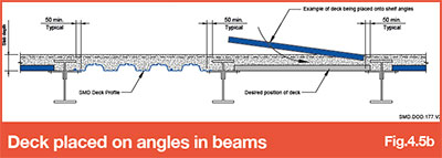
4.5.2 Shelf Angles or bottom flanges
To reduce the structural zone it is sometimes necessary to install the decking onto angles fixed to the beam webs or bottom flanges. Where deck ends are supported on shelf angles or bottom flanges between beam webs, the shelf angle or bottom flanges must be designed to extend a minimum of 50mm beyond the toe of the beam top flange. This minimum dimension of 50mm is essential to enable the sheets to be physically positioned between toes of top flanges and provide access for a cartridge tool to be used to secure the decking into place (Fig 4.5b).
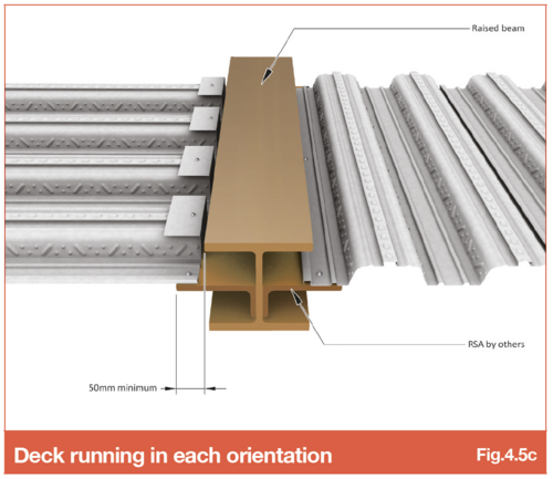
Where the deck spans parallel to the beam web a structural support angle is the recommended detail (Fig 4.5c). It may be possible depending on spacing of secondary beams to utilise a 2.0mm gauge flashing to avoid the requirement for a structural angle, however this will impact on the slab capacity for high concentrated loads locally in the region of the non-structural flashing.
Refer to SMD Data sheet SMD.DOD.177 - Decking Bearing of Shelf Angle
Go to NEXT section