

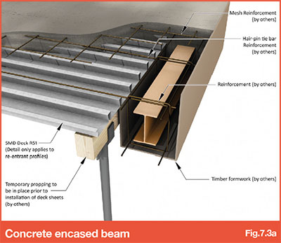
7.3 - Concrete encased beams
In some instances concrete encased perimeter beams may be specified as part of the fire design. It is recommended that the beam is encased to the top flange level off-site, therefore enabling the decking to be installed to the beam top flange as normal.
Where it is not possible to carry out the concrete encasement off-site, the following procedure is possible using R51+ profile:
- • Decking installed to top flange of perimeter beam as normal.
- • The shuttering is then provided by others. This must be designed by the structural engineer to sustain the weight of the decking, wet concrete and construction imposed loads to avoid the temporary propping requirement indicated in Fig 7.3a.
- • Decking is then cut back to the line of the shuttering, with temporary propping in place (if required).
- • In this detail, the decking will not contribute to the shear resistance of the finished slab. Hairpin/tie bar reinforcement in the troughs of the decking profile will need to be designed/specified by the engineer.
A similar process to that detailed above can be followed where a building or basement has perimeter concrete walls with continuity reinforcement extending into the floor slab, providing the formwork is designed to support the weight of the decking, wet concrete and construction imposed loads to avoid the need for adjacent temporary propping.
Go to NEXT section