

Difference between revisions of "4.6 - Fixings"
| Line 3: | Line 3: | ||
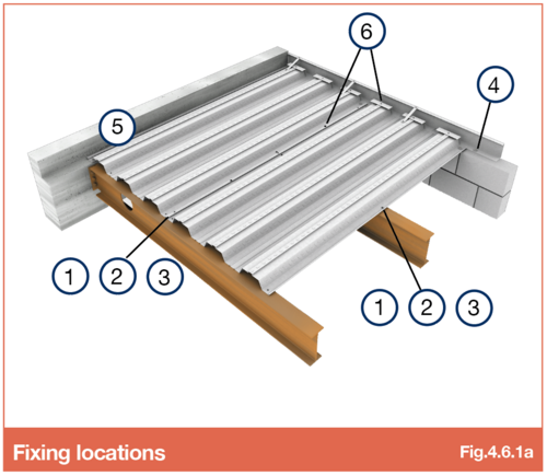
SMD recommend a variety of specialist fixings dependant upon project design, specification, Health and Safety requirements and the situation in which they are being used. | SMD recommend a variety of specialist fixings dependant upon project design, specification, Health and Safety requirements and the situation in which they are being used. | ||
| + | [[File:4.6.1a.png|500px|link=]] | ||
| + | '''Decking to steelwork''' | ||
| − | + | Decking is generally fixed to steelwork using shot or gas fired nails (ref Fig.4.6.1a, Item 1 or 2), as this is the fastest and most cost effective method. Due to design or Health and Safety reasons, shot-fired fixings are in some instances not permitted. | |
| − | + | ||
| + | In such instances self-tapping screw fixings (Item 3) are used, these may require pre-drilled holes in the beam flange (dependant on flange thickness). | ||
| − | |||
| + | '''Item 1 - General purpose nail''' (Ref Fig.4.6.1a) | ||
| − | + | Where steel beams are to receive thru-deck welded shear studs. | |
| − | : | + | [[File:4.6.1a table.png|500px|link=]] |
| − | : | + | '''Important Note:''' Beams to receive shear studs '''MUST''' have the top flanges left unpainted! |
| − | |||
| + | '''Item 2 - Heavy duty nail (19mm long)''' (Ref Fig.4.6.1a) | ||
| − | + | To be used where no shear studs are specified. These fixings provide an increased shear resistance to Item 1. | |
| + | [[File:4.6.1b table.png|500px|link=]] | ||
| − | |||
| − | + | '''Item 3 - Self tapping screw (long)''' (Ref Fig.4.6.1a) | |
| + | Screw fixing deck to steelwork (commonly where shot fired fixings (item 1 or 2) are not permitted or design requires). | ||
| − | [[File:4. | + | [[File:4.6.1c table.png|500px|link=]] |
| − | [[File:4.6b.png| | + | |
| + | '''Decking to Blockwork, Masonry or Concrete''' | ||
| + | |||
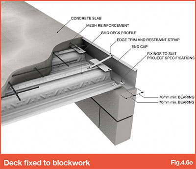
| + | Where decking is fixed to blockwork, masonry or concrete the standard shot-fired fixings (Items 1 and 2 for steel application) are not suitable as these may cause damage to the bearing surface. For fixing to blockwork, an alternative shot-fired fixing (ref Fig.4.6.1a, Item 4 (Table 4.6.1d)) can be used. | ||
| + | |||
| + | Where decking is to be fixed to concrete or masonry, drill, plug and screw type fixings (ref Fig.4.6.1a, Item 5 (Table 4.6.1e)) are recommended. | ||
| + | |||
| + | [[File:4.6e.jpg|500px|link=]] | ||
| + | |||
| + | |||
| + | '''Item 4 - Shot fired nail with plastic washer (~36mm long)''' (Ref Fig.4.6.1a) | ||
| + | |||
| + | Fixing deck, flashing or trim to blockwork or concrete (Shot-fired). | ||
| + | |||
| + | [[File:4.6.1d table.png|500px|link=]] | ||
| + | |||
| + | |||
| + | '''Item 5 Hammer Fixing''' (Ref Fig.4.6.1a) | ||
| + | |||
| + | Fixing deck to concrete or masonry. A hole is drilled through the deck into the concrete/masonry for this fixing to be installed. | ||
| + | |||
| + | [[File:4.6.1e table.png|500px|link=]] | ||
| + | |||
| + | |||
| + | '''Fixings to Timber/Glulam Beams''' | ||
| + | |||
| + | Or where shot-fired fixings are not permitted, self-drilling screws should be used. | ||
| + | |||
| + | [[File:4.6.1f table.png|500px|link=]] | ||
| + | |||
| + | |||
| + | When specifying fixings for a project, the fixing supplier should be consulted to ensure the length of fixing and specification (mentioned above) is appropriate for the support material and grade involved. The above guidance is based on fixing manufacturer’s literature which is subject to change without notice. | ||
| + | |||
| + | |||
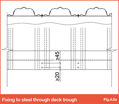
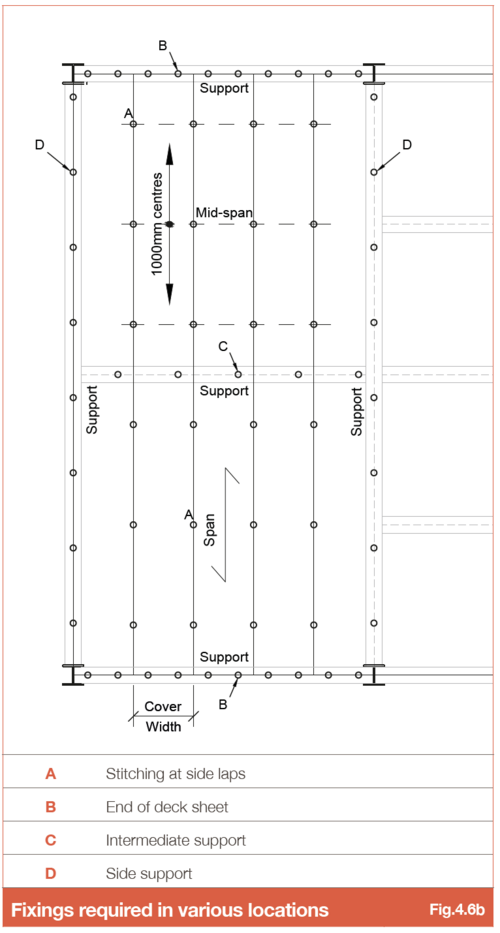
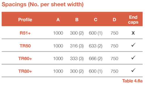
| + | Decking must be fixed to supports at 300mm centres at each sheet end and at 600mm centres over intermediate supports, or closest multiples to suit trough centres, refer to Fig. 4.6b. Fixings should be located a minimum of 20mm from the end of the sheet and where more than one fixing per trough is specified, the spacing between fixings in the direction of the deck span is to be ≥ 45mm. | ||
| + | |||
| + | |||
| + | Where decking is required to provide lateral restraint and no thru-deck welded shear studs are specified, the fixing type should be checked by the engineer, refer to section 4.4. | ||
| + | |||
| + | |||
| + | The use of thru deck welded studs or Hilti HVB Shear Connectors (where specified for composite beam design) will enhance the deck anchorage. | ||
| + | |||
| + | |||
| + | [[File:4.6a.jpg|500px|link=]] | ||
| + | |||
| + | [[File:4.6b.png|500px|link=]] | ||
| Line 44: | Line 92: | ||
| − | === 4.6.4 | + | === 4.6.4 Restraint straps and side stitching === |
| − | + | Metal construction screws (ref Fig.4.6.1a, Item 6 (Table 4.6.4a)) are used to stitch sheets at side lap locations and also to attach restraint straps to the edge trim “tick” and decking. | |
Side-stitching for all floor deck profiles is to be provided at maximum 1.0m centres from mid-span using self-tapping screws (refer mark A in Fig 4.6b). | Side-stitching for all floor deck profiles is to be provided at maximum 1.0m centres from mid-span using self-tapping screws (refer mark A in Fig 4.6b). | ||
| − | + | '''Item 6 - Self tapping Screw''' (Ref Fig.4.6.1a) | |
| + | Side stitching deck, fixing restraint straps and end caps. | ||
| + | |||
| + | [[File:4.6.4a table.png|500px|link=]] | ||
| + | |||
| + | |||
| + | Refer to BS EN 1993 or BS5950 for more information | ||
| − | |||
| + | [[File:4.6a Table.png|500px|link=]] | ||
| − | |||
| + | [[File:4.6b Table.png|500px|link=]] | ||
| − | |||
Revision as of 14:55, 8 April 2022
Contents
4.6.1 Recommended fixings for installing floor decking and edge trim
SMD recommend a variety of specialist fixings dependant upon project design, specification, Health and Safety requirements and the situation in which they are being used.
Decking to steelwork
Decking is generally fixed to steelwork using shot or gas fired nails (ref Fig.4.6.1a, Item 1 or 2), as this is the fastest and most cost effective method. Due to design or Health and Safety reasons, shot-fired fixings are in some instances not permitted.
In such instances self-tapping screw fixings (Item 3) are used, these may require pre-drilled holes in the beam flange (dependant on flange thickness).
Item 1 - General purpose nail (Ref Fig.4.6.1a)
Where steel beams are to receive thru-deck welded shear studs.
Important Note: Beams to receive shear studs MUST have the top flanges left unpainted!
Item 2 - Heavy duty nail (19mm long) (Ref Fig.4.6.1a)
To be used where no shear studs are specified. These fixings provide an increased shear resistance to Item 1.
Item 3 - Self tapping screw (long) (Ref Fig.4.6.1a)
Screw fixing deck to steelwork (commonly where shot fired fixings (item 1 or 2) are not permitted or design requires).
Decking to Blockwork, Masonry or Concrete
Where decking is fixed to blockwork, masonry or concrete the standard shot-fired fixings (Items 1 and 2 for steel application) are not suitable as these may cause damage to the bearing surface. For fixing to blockwork, an alternative shot-fired fixing (ref Fig.4.6.1a, Item 4 (Table 4.6.1d)) can be used.
Where decking is to be fixed to concrete or masonry, drill, plug and screw type fixings (ref Fig.4.6.1a, Item 5 (Table 4.6.1e)) are recommended.
Item 4 - Shot fired nail with plastic washer (~36mm long) (Ref Fig.4.6.1a)
Fixing deck, flashing or trim to blockwork or concrete (Shot-fired).
Item 5 Hammer Fixing (Ref Fig.4.6.1a)
Fixing deck to concrete or masonry. A hole is drilled through the deck into the concrete/masonry for this fixing to be installed.
Fixings to Timber/Glulam Beams
Or where shot-fired fixings are not permitted, self-drilling screws should be used.
When specifying fixings for a project, the fixing supplier should be consulted to ensure the length of fixing and specification (mentioned above) is appropriate for the support material and grade involved. The above guidance is based on fixing manufacturer’s literature which is subject to change without notice.
Decking must be fixed to supports at 300mm centres at each sheet end and at 600mm centres over intermediate supports, or closest multiples to suit trough centres, refer to Fig. 4.6b. Fixings should be located a minimum of 20mm from the end of the sheet and where more than one fixing per trough is specified, the spacing between fixings in the direction of the deck span is to be ≥ 45mm.
Where decking is required to provide lateral restraint and no thru-deck welded shear studs are specified, the fixing type should be checked by the engineer, refer to section 4.4.
The use of thru deck welded studs or Hilti HVB Shear Connectors (where specified for composite beam design) will enhance the deck anchorage.
4.6.2 Wind Loading on temporary fixings
In exposed locations where beams that are to receive shear studs are left un-studded for a notable period of time, temporary fixings mentioned in 4.6.1 should be checked against wind loading. In these situations an enhanced fixing type or closer centres may be required. This subject is currently under investigation by BCSA, see Temporary Fixing of Metal Decking Interim Guidance or contact SMD Technical Team.
4.6.3 Additional fixings for MEWP frame erection
Where the steel contractor is using MEWP frames as part of the erection plan there may be a need to enhance the fixing type or centres. Where applicable, the steel contractor is to confirm the fixing type and centres required and identify the specific locations where MEWP frames are to be used.
4.6.4 Restraint straps and side stitching
Metal construction screws (ref Fig.4.6.1a, Item 6 (Table 4.6.4a)) are used to stitch sheets at side lap locations and also to attach restraint straps to the edge trim “tick” and decking.
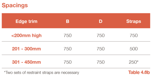
Side-stitching for all floor deck profiles is to be provided at maximum 1.0m centres from mid-span using self-tapping screws (refer mark A in Fig 4.6b).
Item 6 - Self tapping Screw (Ref Fig.4.6.1a)
Side stitching deck, fixing restraint straps and end caps.
Refer to BS EN 1993 or BS5950 for more information
Go to NEXT section