Difference between revisions of "6.5 - BS5950-3 Section 3.1 Reduction factors for SMD Products"
From TGN Online
(Created page with "[https://smdltd.co.uk/technical-info/Contents '''Back to main Contents page'''] Body - First line Body - Last line ---- '''Other items within 6.0 - Design - Floor de...") |
|||
| Line 3: | Line 3: | ||
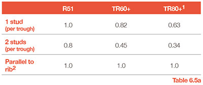
| − | + | These figures are calculated in accordance with the latest revision of BS5950-3 Section 3.1:1990 +A1 2010. The factors in this table should be applied to the minimum resistance for a stud in a solid slab (Qk) from Table 5 of BS5950-3 Section 3.1:1990 +A1 2010. | |
| − | + | [[File:6.5a.jpg|400px]] | |
| + | : 1 = Figures are based on 95mm LAW shear studs except TR80+ which is based on 120mm LAW. | ||
| + | : 2 = All factors are based on ‘mesh at nominal top cover’, except Parallel which is based on ‘below head of stud’ | ||
| − | - | + | |
| + | '''Refer to SCI Publication PN001a-GB NCCI: Resistance of headed stud shear connectors in transverse sheeting''' | ||
| + | '''Refer to SCI Publication PN002a-GB NCCI: Modified limitation on partial shear connection in beams for buildings''' | ||
| − | ''' | + | '''Refer to SCI AD380: What Height of Shear Stud Should be used in Eurocode 4''' |
| − | ''' | + | '''Refer to SCI AD174: Shear connection along composite edge beams''' |
| − | |||
| − | + | ---- | |
| − | + | ||
| − | + | ||
| − | + | ||
| − | + | ||
| − | + | ||
| − | + | ||
| − | + | ||
| − | + | ||
| − | |||
| − | + | Other items within 6.0 - Design - Floor deck Composite beam design:- | |
| + | : [[6.0 - Design - Floor deck composite beam design]] | ||
| + | : [[6.1 - Shear stud LAW (length after weld)]] | ||
| + | : [[6.2 - Design rules for minimum degree of connection]] | ||
| + | : [[6.3 - Shear stud reduction factors]] | ||
| + | : [[6.4 - BS EN 1994-1-1 Reduction factors for SMD Products]] | ||
| + | : [[6.5 - BS5950-3 Section 3.1 Reduction factors for SMD Products]] | ||
| + | : [[6.6 - Shear stud spacing]] | ||
| + | : [[6.7 -Transverse reinforcement for composite beams]] | ||
| + | : [[6.8 - Alternative Shear Connectors]] | ||
Revision as of 11:29, 25 January 2017
These figures are calculated in accordance with the latest revision of BS5950-3 Section 3.1:1990 +A1 2010. The factors in this table should be applied to the minimum resistance for a stud in a solid slab (Qk) from Table 5 of BS5950-3 Section 3.1:1990 +A1 2010.
- 1 = Figures are based on 95mm LAW shear studs except TR80+ which is based on 120mm LAW.
- 2 = All factors are based on ‘mesh at nominal top cover’, except Parallel which is based on ‘below head of stud’
Refer to SCI Publication PN001a-GB NCCI: Resistance of headed stud shear connectors in transverse sheeting
Refer to SCI Publication PN002a-GB NCCI: Modified limitation on partial shear connection in beams for buildings
Refer to SCI AD380: What Height of Shear Stud Should be used in Eurocode 4
Refer to SCI AD174: Shear connection along composite edge beams
Other items within 6.0 - Design - Floor deck Composite beam design:-
- 6.0 - Design - Floor deck composite beam design
- 6.1 - Shear stud LAW (length after weld)
- 6.2 - Design rules for minimum degree of connection
- 6.3 - Shear stud reduction factors
- 6.4 - BS EN 1994-1-1 Reduction factors for SMD Products
- 6.5 - BS5950-3 Section 3.1 Reduction factors for SMD Products
- 6.6 - Shear stud spacing
- 6.7 -Transverse reinforcement for composite beams
- 6.8 - Alternative Shear Connectors


