

6.6 - Shear stud spacing
In accordance with BS EN 1994-1-1 or BS5950-3 Section 3.1:1990+A1 2010, the dimensions and configurations shown in Figs 6.6a to 6.6f must be followed to ensure the welded shear studs are effective to provide the documented stud resistance values.
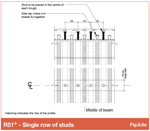
Refer SMD Detail Sheet SMD.DOD.185 - R51 Single studs
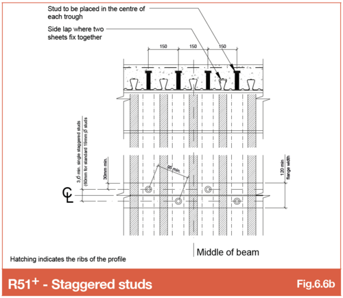
Refer SMD Detail Sheet SMD.DOD.183 - R51 Staggered studs
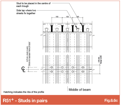
Refer SMD Detail Sheet SMD.DOD.184 - R51 Studs in pairs
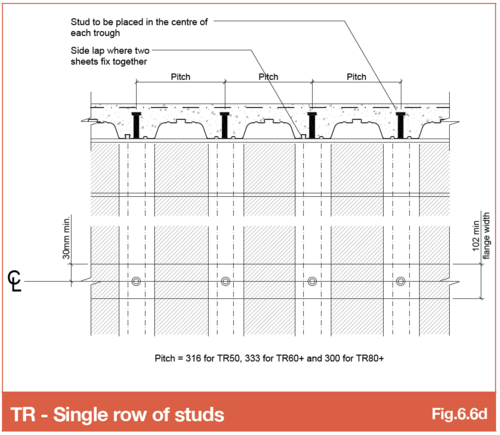
Refer SMD Detail Sheet SMD.DOD.182 - TR+ Single studs
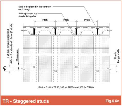
Refer SMD Detail Sheet SMD.DOD.180 - TR+ Staggered studs
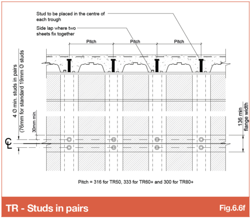
Refer SMD Detail Sheet SMD.DOD.181 - TR+ Studs in pairs
6.6.1 Studs to raking beams
The quantity or spacing of shear studs that are required to be welded to each of the beams in a steel frame for a composite slab, are typically specified by the structural engineer. These are noted in a variety of ways on the engineers beam layout general arrangement drawings, but most commonly by a note next to each beam indication the quantity of shear studs for that beam, or the spacing between the of studs along the beam. When SMD add the shear stud labels to our drawings, we work to the information from the engineer’s drawings.
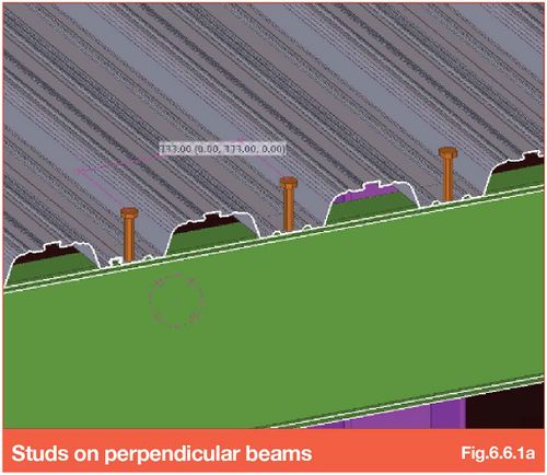
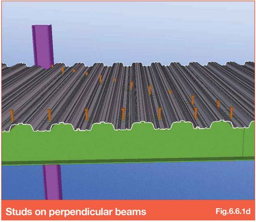
For example, with SMD TR60+ profile, the deck troughs fall at 333mm centres. The studs must be installed in the troughs, so to beams perpendicular to the deck span, the studs could be specified at 333mm centres (i.e. 1 per trough). The quantity of studs would therefore be approximately the length of the beam divided by 333mm.
Studs at 333mm centres to beam perpendicular to deck span
One issue that often arises is that no consideration has been made to beams that are raking to the decking span.
If the engineer or the related design software just calculates studs based on the beam length and the spacing, it will not calculate correctly for beams that are raking to the deck span.
Studs at 333mm centres perpendicular to the beam
The dotted centre lines show the location of the deck troughs and therefore where the shear studs must be located on the beam.
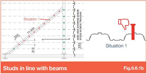
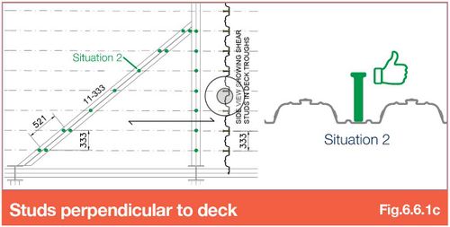
Trying to instal 11 studs at 333mm centres in line with the angle of the beam is not possible (studs shown red where they cannot be installed).
In the example shown and due to the angle of the beam, the deck troughs effectively fall at 213mm centres perpendicular to span and not in the deck troughs.
Studs at 333mm centres perpendicular to the deck (not the beam)
Placing shear studs on the centre line of the deck troughs and in line with the raking beams, means the studs are actually located 521mm apart (and not 333mm in relation to the angle of the beam).
If it is essential to achieve the quantity of studs on the beam, and the beam flanges are wide enough, studs in pairs will be installed at each end of the beam until the correct number of studs have been installed.
Stud number and spacing considerations
Consideration should be made when specifying the shear stud quantity/spacing on a steel frame that has beams that are raking to deck span.
Particular attention should be made on raking beams with narrow beam flanges as it may be impossible to double up studs (in pairs) at each end of the beam due to the flange width (shear studs require a minimum of 76mm gap between each stud when placed in pairs - see Fig.6.6c and Fig.6.6f).
Go to NEXT section