

6.6 - Shear stud spacing
In accordance with BS EN 1994-1-1 or BS5950-3 Section 3.1:1990+A1 2010, the dimensions and configurations shown in Figs 6.6a to 6.6f must be followed to ensure the welded shear studs are effective to provide the documented stud resistance values.
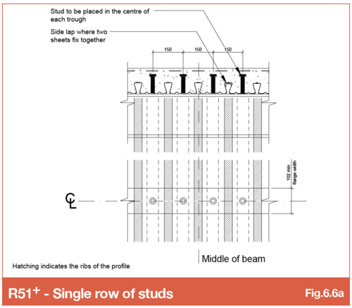
Refer SMD Detail Sheet SMD.DOD.185 - R51 Single studs
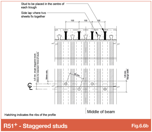
Refer SMD Detail Sheet SMD.DOD.183 - R51 Staggered studs
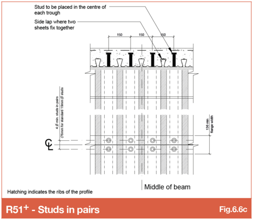
Refer SMD Detail Sheet SMD.DOD.184 - R51 Studs in pairs
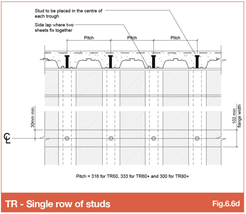
Refer SMD Detail Sheet SMD.DOD.182 - TR+ Single studs
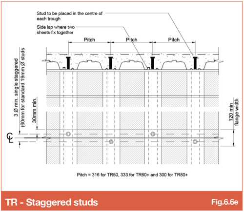
Refer SMD Detail Sheet SMD.DOD.180 - TR+ Staggered studs
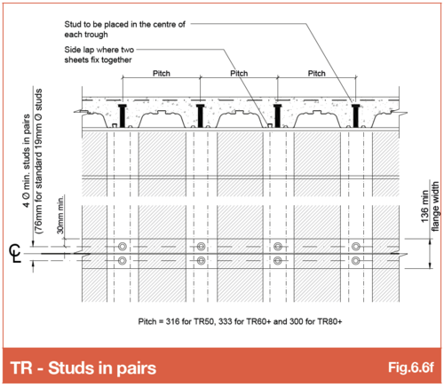
Refer SMD Detail Sheet SMD.DOD.181 - TR+ Studs in pairs
6.6.1 Studs to raking beams
The quantity or spacing of shear studs required on composite steel beams are specified by the steel designer. This is typically the structural engineer with the quantity or spacing of studs indicated as a note against each individual beam on the steel general arrangement drawing. SMD, where contracted, add shear stud labels to the deck general arrangement drawings using the information specified by the steel designer.
It is important where steel beams are raking across the deck span to consider the impact this has on stud numbers or spacings achievable due to the increase in the distance between troughs caused by the angle of the rake. Some steel frame design software packages only consider stud numbers in relation to beam length and requirement for the composite beam design without considering a raking deck orientation or whether it is possible to get the studs onto the beam where the deck is raking. Detailed below are examples where this issue needs consideration.
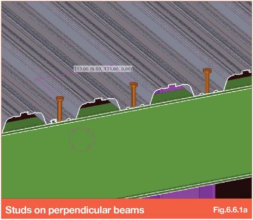
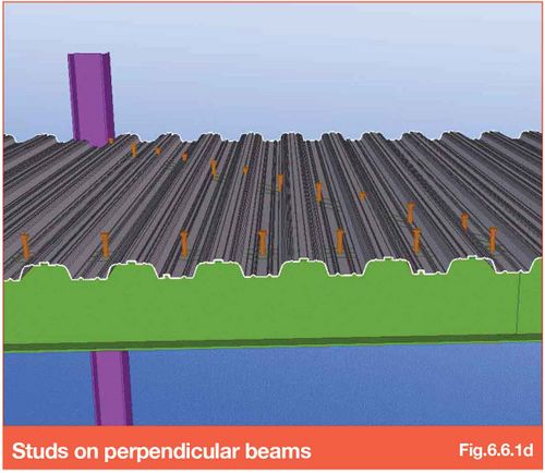
Studs at 333mm centres to beam perpendicular to deck span
SMD TR60+ profile has deck troughs at 333mm, meaning where deck is perpendicular to the beam CL, studs must be detailed at 333mm. The quantity of studs achievable in this situation is essentially beam length divided by 333. This can be increased by detailing pairs per trough if the beam width permits
Studs at 333mm centres along the raking beam
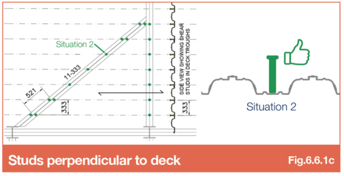
The dotted centre lines show the location of the deck troughs and therefore where the shear studs must be located on the beam.
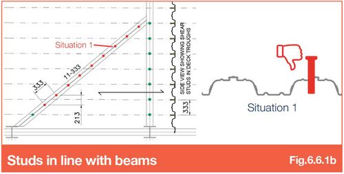
Trying to instal 11 studs at 333mm centres in line with the angle of the beam is not possible (studs shown red where they cannot be installed).
In the example shown and due to the angle of the beam, the studs effectively fall at 213mm centres perpendicular to span which is not in the deck troughs and, hence, not achievable.
Studs at 333mm centres perpendicular to the deck (not the beam)
Placing shear studs on the centre line of the deck troughs and in line with the raking beams, means the studs are actually located 521mm apart (and not 333mm due to the angle of the beam).
If it is essential to achieve the quantity of studs on the beam, and the beam flanges are wide enough, studs in pairs can be installed at each end of the beam to achieve the correct number of studs. This will need to be checked by the steel beam designer as each stud in a pair provides a lower resistance than a single stud. Therefore, the number may need to be increased for this configuration.
Stud number and spacing considerations
Consideration should be made when specifying the shear stud quantity/spacing on a steel frame that has beams that are raking to deck span.
In summary, it is important to consider raking beams and influence on number/spacings when specifying shear studs on beams that are not perpendicular or parallel to the deck span. Particular attention should be made on raking beams with narrow top flanges as it may be impossible to double up studs (in pairs) due to the flange width. Where beams are wider it may be possible to separate the deck along the CL of beam with closure flashings to enable studs to be installed - contact SMD Technical team for further guidance.
Go to NEXT section