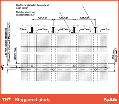
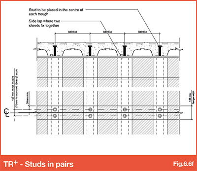
6.6 - Shear stud spacing
From TGN Online
Revision as of 11:30, 25 January 2017 by Admin (Talk | contribs) (Created page with "'''Back to main Contents page''' In accordance with BS EN 1994-1-1 or BS5950-3 Section 3.1:1990+A1 2010, the dimensions and configurations shown in Figs 6.6a to 6.6f...")
Back to main Contents page
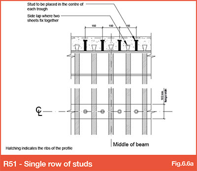
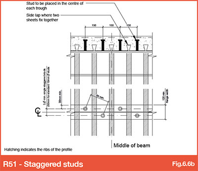
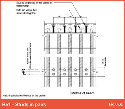
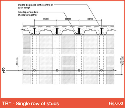
In accordance with BS EN 1994-1-1 or BS5950-3 Section 3.1:1990+A1 2010, the dimensions and configurations shown in Figs 6.6a to 6.6f must be followed to ensure the welded shear studs are effective to provide the documented stud resistance values.
Other items within 6.0 - Design - Floor deck Composite beam design:-
- 6.0 - Design - Floor deck composite beam design
- 6.1 - Shear stud LAW (length after weld)
- 6.2 - Design rules for minimum degree of connection
- 6.3 - Shear stud reduction factors
- 6.4 - BS EN 1994-1-1 Reduction factors for SMD Products
- 6.5 - BS5950-3 Section 3.1 Reduction factors for SMD Products
- 6.6 - Shear stud spacing
- 6.7 -Transverse reinforcement for composite beams
- [[6.8 - Alternative Shear Connectors]


