

11.0 - Installation - Floor deck and shear studs
SMD products should only be installed by those competent and trained to do so. Specific reference should also be given to the BCSA Code of Practice for Metal Decking and Stud Welding and, as a minimum, the following procedure should be followed.
Contents
- 1 11.0 - Installation - Floor Deck and Shear Studs
- 1.1 11.0.1 - Pre-start
- 1.2 11.0.2 - Weather conditions
- 1.3 11.0.3 - Supporting structure
- 1.4 11.0.4 - Perimeter Edge Protection
- 1.5 11.0.5 - Access to level
- 1.6 11.0.6 - Manual Handling
- 1.7 11.0.7 - Laying decking sheets
- 1.8 11.0.8 - Cutting / notching
- 1.9 11.0.9 - Deck fixings
- 1.10 11.0.10 - Side laps
- 1.11 11.0.11 - Sealing and finishing off
- 1.12 11.0.12 - Edge trim
- 1.13 11.0.13 - Forming holes and openings
11.0 - Installation - Floor Deck and Shear Studs
11.0.1 - Pre-start
Prior to commencement of deck installation, a system of fall protection (refer section 10) and safe access must be in place. This should form part of the overall safe system of work agreed by all parties and detailed in the project specific Risk Assessment and Method Statement (RAMS).
11.0.2 - Weather conditions
Decking bundles should only be opened if all the sheets in the bundle can be fixed or left in a safe condition at the end of the shift. Consideration must be given during periods of bad weather to any unfixed sheets as these must be secured at the end of each day by using a temporary strap secured to the frame or decking.
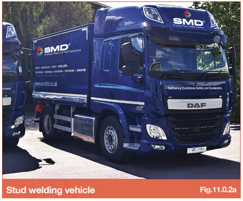
Ground conditions for stud welding vehicles
Stud welding vehicles have standard road suspension and tyres, suitable ground conditions are essential for safe access to the site to allow stud welding works to be carried out. With a gross weight of 19 tonne HGVs are 7.00m long 2.50m wide 3.50m high and need to be positioned within 6m of the steel frame and so that the distance between the generator and the stud welding work does not exceed 60 metres.
A visual inspection is often adequate however, it is essential that the assessment is made by persons with relevant knowledge and experience to know when further expert advice and assessment is required.
Ground bearing capacity can also change throughout the project with weather & site conditions such as new excavations, a view of the conditions needs to be an on-going activity.
It is important to note if the ground conditions are unsuitable on our arrival to site, for Health and Safety reasons ours teams will not be able to carry out their works, which in turn could lead to additional delays and costs.
11.0.3 - Supporting structure
Where supports are to receive shear studs, top flanges must be unpainted and free from grease or rust that might adversely affect the weld. Refer to Fixings Section 4.6 for guidance on minimum bearings.
11.0.4 - Perimeter Edge Protection
Edge protection must be installed prior to the decking Installation commencing to all edge beams, voids and openings to prevent falls from height. Phase edges may also require protection where catch nets are not used or suitable.
Types of handrail options are listed below to also include and the use of structural elements (e.g. cladding rails). It is important that edge protection is designed to allow deck, trim and shear studs (where required) can be installed safely. The following key points however apply regardless of the type of handrail adopted:
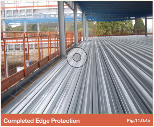
Completed Edge Protection - Ensure that edge protection is inspected, complete and secure on completion, before use and at 7 days intervals.
SMD will not alter or move edge protection. Changes must be undertaken by trained competent person(s)/supplier.
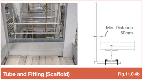
Tube and Fitting (Scaffold) - Handrails to be placed in accordance with the slab location as detailed on SMD drawings. Handrails should provide sufficient access to the full extent where SMD are required to place edge trim (handrails should not be in locations where they could hinder the installation of edge trim/shear studs), allow 50mm clearance as noted in detail. Ensure installation is carried out by a competent supplier. The top rail must be a minimum of 950mm high & the gaps between hand rails must not exceed 470mm.
Handrails are fixed to the underside on the beam, ensuring the top of flange free from obstructions. System must be installed PRIOR to Netting.
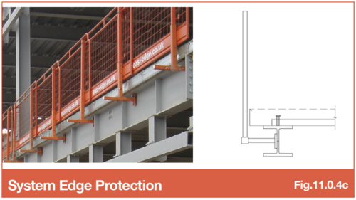
System Edge Protection - Position hand railing to the outside face of the columns/beams on cantilever brackets to preclude the need for operatives to lean through the hand railing to fix the edge trims and the requirement for notching decking. Allow sufficient clearance between inside face of handrail & dimensioned trim position, see Detail 2 or set at 470mm from the top of the steel.
Handrails are fixed to the beam web or underside of the beam, ensuring the top of flange free from obstructions.
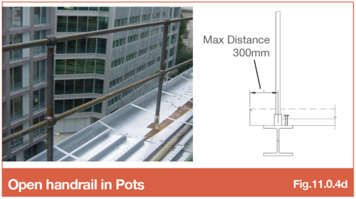
Open handrail in Pots - Positioning hand railing on CL of beams necessitates operatives having to lean through the hand railing to fix the edge trims & straps. Maximum gaps must not exceed 470mm.
Adds the requirement for notching decking and can create problems when using catilevered deck or large bottom leg trim (Max. 300mm distance). Handrails are placed in “pots” on the top of the beam flange which creates installation obstructions.
11.0.5 - Access to level
Falls from height are the largest single cause of accidental death in the construction industry & account for 50% of all deaths. Accidents involving falls can be prevented if an effective system of work is planned & implemented.
Whilst fall protection during work activities is generally well planned & organised it is often the access to the level of work that causes the most significant hazard.
Access positions should be planned to ensure they correspond with decking setting out point at each level which will reduce the need to traverse the open steel frame. Acceptable access methods during the installation of metal decking & shear studs, in order of preference;
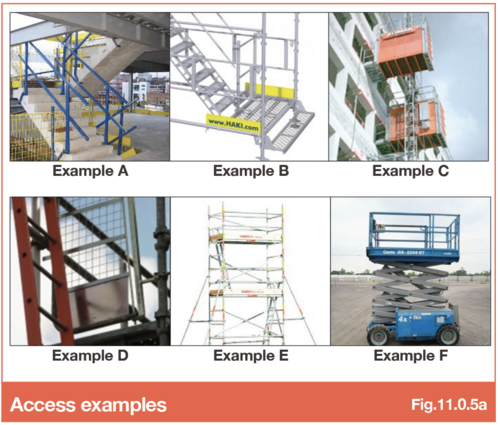
A - Permanent Stair Access
- Positive Points - Stable & secure. Allows movement of operatives & small tools & material with minimal risk.
- Negative Points - Programme dependant. Falls on stairs can be an issue. Consider mobile telephone ban.
B - Temporary Stair Tower
- Positive Points - Stable & secure. Allows movement of operatives & small tools & material with minimal risk.
- Negative Points - Need to be planned & erected by competent teams. Weekly inspections. May obstruct other trades. Falls can be an issue. Consider mobile telephone ban.
C - Mechanical Hoist
- Positive Points - Stable & secure. Allows movement of operatives & small tools & material with minimal risk.
- Negative Points - Need to be planned & often only viable to give access onto concreted floor plates after decking activities complete.
D - Access Ladder
- Positive Points - Only give short term duration access for operatives.
- Negative Points - Movement of small tools & materials is hazardous whilst maintaining 3 point contact. Gates & step of points need to be considered.
E - Aluminium Access Tower Scaffold
- Positive Points - Stable & secure. Allows movement of operatives.
- Negative Points - Need to be planned & erected by competent teams. Weekly inspections. May obstruct other trades. Movement of small tools and materials is very difficult due to configuration of access hatches, ladders etc.
F - MEWP or Scissor Lifts
- Positive Points - NA.
- Negative Points - We do not advocate the use of MEWP or Scissor Lifts for access to Level
11.0.6 - Manual Handling
The Manual Handling Operations Regulations 1992 place a legal responsibility on employers to ensure that any manual handling operations are eliminated, so far as is reasonably practicable.
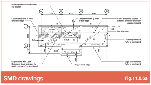
SMD drawings
- Positive Points - The majority of manual handling can be eliminated from the process by ensuring that the decking bundles are loaded out in accordance with SMD layout drawings.
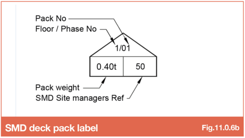
SMD drawing labels (deck packs)
- Positive Points - Bundle reference icon on deck layout drawings is pointed on one side. The “point” indicates the location of the paint stripe when the packs are loaded out, this MUST face the setting out point (SOP).
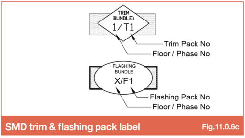
SMD drawing labels (trim and flashing packs)
- Positive Points - Edge trims and Flashing Bundles must be lifted to level by mechanical means & located in accordance with SMD layout drawings.
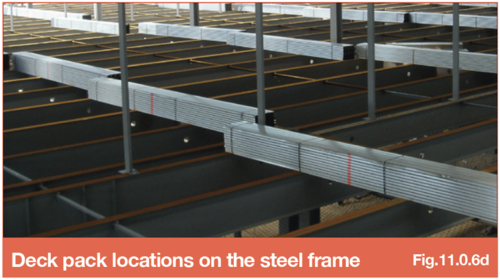
Deck pack locations on the steel frame
- Positive Points - Bundles should be positioned such that all the interlocking side laps are on the same side, this enable the decking to be laid progressively without the need to turn the sheets. To assist with this the decking bundles will come with a paint stripe down one side.
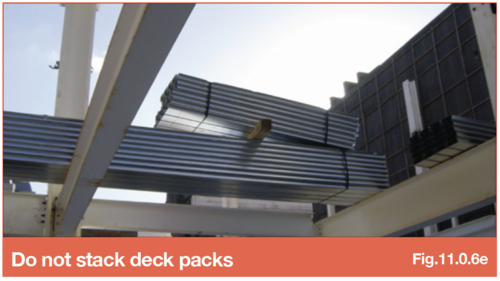
- Bad Example - Stacking multiple packs of decking on top of one another is not acceptable.
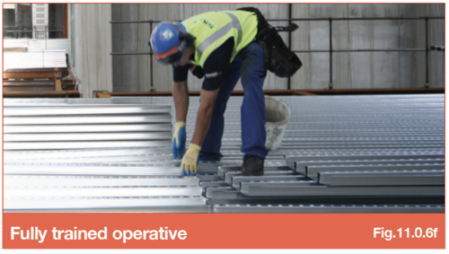
Fully trained workforce
- Positive Points - All decking operatives will have received manual handling training.
- All decking operatives must be issued with and instructed to wear the correct PPE including suitable gloves for handling decking and edge trims, as they have intrinsically sharp edges until they are fixed into position. Steel toe cap boots must be worn at all times.
Moving stud barrels
- Positive Points - Shear studs must be lifted to level by mechanical means (by the client).
- Bad Points - Carrying studs up stairs or ladders in small quantities is not acceptable.
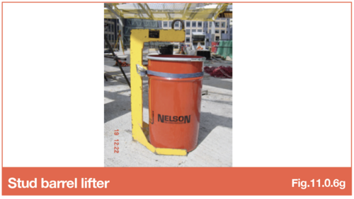
Refer to Section 9.5 Lifting Shear Studs to Level for more information.
11.0.7 - Laying decking sheets
Using the access provided, the installer should straddle the first bundle of decking to remove the banding. The first decking sheet will then be pushed out onto the steelwork to be used as a working platform from which to lay the remaining sheets in that bay. Decking sheets should then be lapped, lined up and fixed into place once the adjacent bay has been laid and the troughs of the decking have been lined through. During installation, cumulative measurements of across the bay width should be taken to ensure the effective product cover width is consistently achieved.
11.0.8 - Cutting / notching
Decking sheets are typically delivered to site at the correct square cut length. Where decking ribs sit over beams that are to receive welded shear studs, around columns and other protrusions, notching and/or cutting of the deck will be required. This should be carried out by trained operatives using suitable disc cutters (petrol, cordless, electric or pneumatic) with appropriate blade, plasma cutters or similar approved equipment. For some contracts, cutting will be carried out off-site prior to delivery (refer to section 13.5), in these instances the sheets will be delivered to site at the correct length and shape for installation with only minor notching required around columns and handrails.
11.0.9 - Deck fixings
Fixing of the deck and edge trim to the supporting steelwork or walls will typically be carried out using low velocity powder (‘shot-firing’) or gas-actuated cartridge tools. In certain circumstances, the use of self-tapping screws may be necessary.
Refer to Section 4.6 - Fixings for recommended fixing types and spacings.
11.0.10 - Side laps
At side laps, the deck sheets must be stitched together using self-tapping screws, installed with suitable screw guns, at maximum 1.0m centres. In addition to stabilising the joint, these help minimise grout loss experienced during concreting.
11.0.11 - Sealing and finishing off
Gaps up to 5mm are acceptable as they are not sufficient to allow concrete aggregate to escape.
The decking is not intended to provide a watertight finish and a degree of fines and water seepage (grout loss) is to be expected from the panel ends and joints.
In areas where it is essential to reduce grout loss to a minimum, the addition of tape at all butt joints and side laps may offer an economical solution, it should be noted that this is not standard practice and must be discussed at pre-tender stage.
11.0.12 - Edge trim
Generally supplied in 3.00m standard lengths, each length should be tethered during installation using the holes provided. The edge trim must be fixed to the perimeter supports at maximum 750mm centres, with restraint straps installed to the top of the upstand leg/tick at centres as indicated in the Edge Trim & Flashings section using self-tapping screws.
11.0.13 - Forming holes and openings
Where trimming steels are provided, the decking sheets may be cut to suit the size of the opening and edge trim installed. Where there is no supporting steelwork, the voids will have to be decked over. The opening should then be formed by the concreting contractor who will box out the opening prior to pouring the concrete.
Refer to Section 5.6 - Forming service holes for more information.
It is the Steelwork Contractors responsibility to ensure the supporting structure is in a stable condition, adequately restrained and handed over as 'safe to access' prior to proceeding with the deck installation. Any additional support plates or angles required around columns, penetrations or splices must also be provided by the Steelwork Contractor.
Refer to Section 11.9 Void Protection and 11.10 VoidSafe® Protection System for more information.
Refer to BS EN 1993 or BS5950 in Lateral Restraint section for more information
Go to NEXT section