Difference between revisions of "8.13 - Fixing specification"
| Line 20: | Line 20: | ||
'''Note:''' The above fixing types and centres (from Table 8.14a) will need specific checks for any uplift or diaphragm design required. This may result in a different fixing type or spacing being required to suit the design situation. For all fixing checks carried out, the performance data for the fixings should be tested in accordance with ECCS publication No. 124. | '''Note:''' The above fixing types and centres (from Table 8.14a) will need specific checks for any uplift or diaphragm design required. This may result in a different fixing type or spacing being required to suit the design situation. For all fixing checks carried out, the performance data for the fixings should be tested in accordance with ECCS publication No. 124. | ||
| + | |||
| + | |||
| + | |||
| + | === 8.13.1 Fixing Centres and Locations === | ||
| + | |||
| + | Recommended minimum fixing centres for each profile are detailed in the table below. These may need to be increased in frequency and/or number where wind uplift load or diaphragm roof design is required – contact SMD Technical Team for further information. | ||
| + | |||
| + | |||
| + | [[File:8.13a-table.jpg|400px]] | ||
| + | |||
| + | |||
| + | [[File:8.13a.jpg|400px]] | ||
| + | |||
| + | |||
| + | The below restrictions on fixing position within the sheet are based on fixing types documented above, BS EN 1993-1-3 recommendations and Hilti literature in relation to cartridge fired pins. | ||
| + | |||
| + | |||
| + | Minimum edge/end distance and spacing | ||
| + | : • Fixing to end of sheet (A): 20mm minimum | ||
| + | : • Fixing to edge of support (B): 10mm minimum (based on steel flanges >7mm) | ||
| + | : • Distance between two fixings (C): 20mm minimum | ||
| + | : • Fixing to edge of sheet (D): 10mm minimum | ||
| + | |||
| + | |||
| + | [[File:8.13b.jpg|400px]] | ||
| + | |||
| + | |||
| + | |||
| + | === 8.13.2 Exposed soffit === | ||
| + | Where the SR sheets are required to provide an exposed soffit a thicker gauge should be considered, as thinner gauges can be susceptible to marking when subjected to relatively high impact loads during construction. | ||
| + | |||
| + | |||
| + | |||
| + | === 8.13.3 Flashing details === | ||
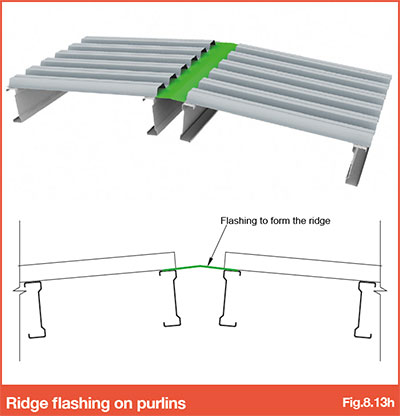
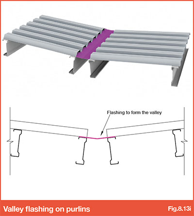
| + | Due to the fixed trough centres and cover widths of the structural roof deck sheets, there are a number of flashings that must be used to close the profile off at perimeter edges and ridges in the roof. The standard details including flashings are detailed below: | ||
| + | |||
| + | |||
| + | |||
| + | [[File:8.13c.jpg|400px]] | ||
| + | |||
| + | |||
| + | [[File:8.13d.jpg|400px]] | ||
| + | |||
| + | Fig.8.14d – Flat plate flashing (RED) and 'Z' shaped flashing (GREEN) at Side Supports | ||
| + | |||
| + | |||
| + | [[File:8.13e.jpg|400px]] | ||
| + | |||
| + | [[File:8.13f.jpg|400px]] | ||
| + | |||
| + | [[File:8.13g.jpg|400px]] | ||
| + | |||
| + | [[File:8.13h.jpg|400px]] | ||
| + | |||
| + | [[File:8.13i.jpg|400px]] | ||
Revision as of 13:00, 25 January 2017
Back to main Contents page
The fixing options selected depend on the function they perform and supports to which they are being installed.
Hot Rolled Steel Sections:
- • Shot-fired Hilti X-ENP-19 L15
- • 5.5mm carbon steel drill screws, or stainless steel for more aggressive environments
Cold-formed Steel Purlins:
- • 5.5mm carbon steel drill screws, or stainless steel for more aggressive environments
Timber and/or Glulam Beams:
- • 6.5mm stainless steel screws
Side stitching of sheets and/or flashings:
- • 4.8mm carbon steel drill screws, or stainless steel for more aggressive environments
Note: The above fixing types and centres (from Table 8.14a) will need specific checks for any uplift or diaphragm design required. This may result in a different fixing type or spacing being required to suit the design situation. For all fixing checks carried out, the performance data for the fixings should be tested in accordance with ECCS publication No. 124.
8.13.1 Fixing Centres and Locations
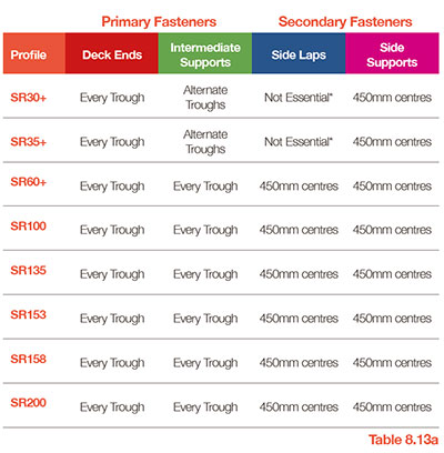
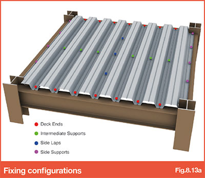
Recommended minimum fixing centres for each profile are detailed in the table below. These may need to be increased in frequency and/or number where wind uplift load or diaphragm roof design is required – contact SMD Technical Team for further information.
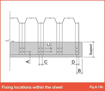
The below restrictions on fixing position within the sheet are based on fixing types documented above, BS EN 1993-1-3 recommendations and Hilti literature in relation to cartridge fired pins.
Minimum edge/end distance and spacing
- • Fixing to end of sheet (A): 20mm minimum
- • Fixing to edge of support (B): 10mm minimum (based on steel flanges >7mm)
- • Distance between two fixings (C): 20mm minimum
- • Fixing to edge of sheet (D): 10mm minimum
8.13.2 Exposed soffit
Where the SR sheets are required to provide an exposed soffit a thicker gauge should be considered, as thinner gauges can be susceptible to marking when subjected to relatively high impact loads during construction.
8.13.3 Flashing details
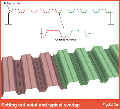
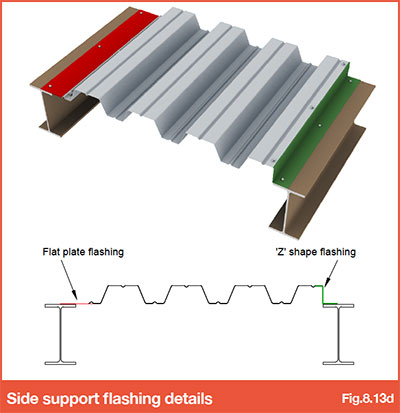
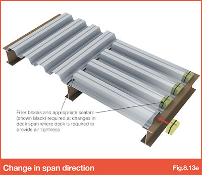
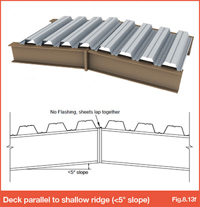
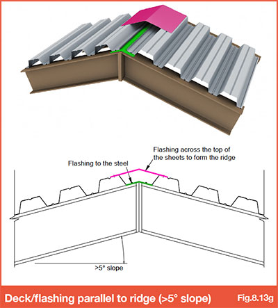
Due to the fixed trough centres and cover widths of the structural roof deck sheets, there are a number of flashings that must be used to close the profile off at perimeter edges and ridges in the roof. The standard details including flashings are detailed below:
Fig.8.14d – Flat plate flashing (RED) and 'Z' shaped flashing (GREEN) at Side Supports
Other items within 8.0 - Design - Roof deck:-
- 8.0 - Design - Roof deck
- 8.1 - Quality
- 8.2 - Spans
- 8.3 - Loads
- 8.4 - Standard end laps
- 8.5 - Extended end laps
- 8.6 - Raking supports and cutting
- 8.7 - Cantilevers
- 8.8 - Sheet lengths
- 8.9 - Fire rating
- 8.10 - Durability
- 8.11 - Acoustics
- 8.12 - Airtightness
- 8.13 - Fixing specification
- 8.14 - Non-fragility
- 8.15 - Diaphragm design
- 8.16 - Protex® warranted insulated system
- 8.17 - Aesthetics


