

5.3 - Fire
The fire design of a composite slab uses one of two approaches:
Steel Fabric (mesh) and Deck Only:
Known and selectable in SMD Elements ® software as ‘Eurocode NCCI Method’ for BS EN 1994 design or ‘Simplified Method’ for BS5950, this method utilises the deck and reinforcement mesh only at the elevated temperatures appropriate for the fire period selected.

To use this method, the composite slab and mesh reinforcement (not necessarily the metal deck) must be continuous over one or more internal supports. Continuity is taken to include all end bay conditions.
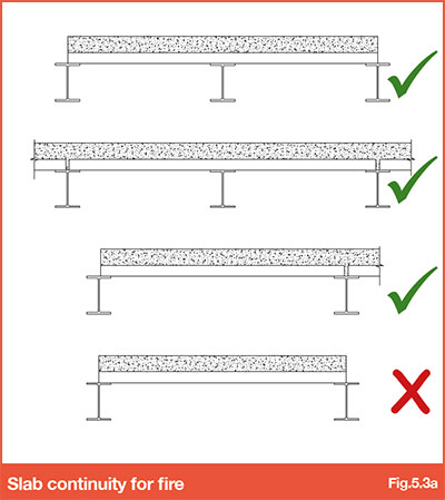
This method will usually give the most economic design, but is limited to fire rating periods of 2 hours or less.
SMD design tables are based on this approach with the slab continuous at one end only. It is important to note this when utilising the tables provided.
Refer to SMD Elements ® design software to create calculations
Fire engineering method:
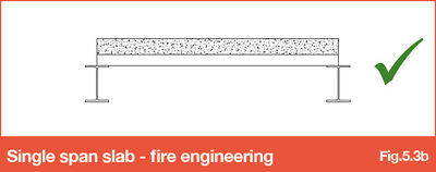
Known (and selectable in SMD Elements® software) as ‘Eurocode Standard Method’ for BS EN 1994 design or ‘Fire Engineering’ for BS5950, this method uses additional reinforcement in the troughs of the decking along with top mesh reinforcement (where slab continuity permits) to achieve the required fire rating. Where the composite slab is true single span (i.e. no slab continuity at either end), this method should be used.
SMD Elements ® design software enables the user to check designs using any of these methods to suit the design standard chosen.
For extensive guidance on the fire design methods mentioned above, refer to Eurocode NCCI PN005c-GB for Eurocode and SCI Publication Publication P-056 for BS5950 design.
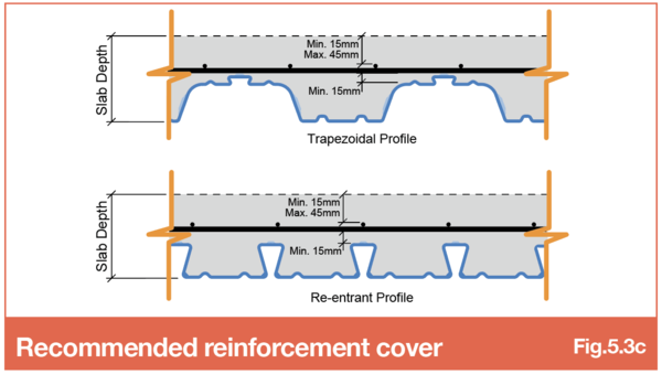
The recommended top cover to the mesh reinforcement is a minimum of 15mm and a maximum of 45mm to ensure the mesh is effective for both the fire and crack-control requirements, refer to Fig.5.3c. Due to the modular size of spacers available and relatively thin concrete depth over the top of the deck rib, in some instances, it may be necessary to position the reinforcement directly on the top of the deck rib. Where this is proposed, it is important that the composite slab design is checked to ensure this does not affect the fire design for the slab design criteria in consideration and that the top cover to reinforcement does not compromise the crack-control provided.
Calculating mesh cover and/or spacer size required
When specifying the mesh top cover it is important to consider whether i) this can be achieved in the thickness of slab over the ribs of the profile and ii) that appropriate reinforcement spacers are available to facilitate the top cover specified. To check this, the following rule of thumb calculations should be followed:
- Maximum top cover achievable = Slab Depth – Overall Deck Depth – (3 x mesh bar size)*
- Reinforcement spacer size required = Slab Depth – Overall Deck Depth – Top Cover – (3 x mesh bar size)*
Overall Deck Depth is from the bottom to very top of the profile (including any top stiffener and/or embossment), for SMD shallow deck profiles this is:
- R51+ = 55mm
- TR50 = 50mm
- TR60+ = 75mm
- TR80+ = 95mm
Mesh bar size = diameter of bar used in the mesh (A142 = 6mm, A193 = 7mm, A252 = 8mm and A393 = 10mm). Slab Depth and Top Cover as indicated in Fig. 5.3c
'* The mesh bar size is multiplied by 3 due to nesting of mesh at laps and assumes that flying end mesh (as recommended) is being used.
For minimum mesh lap requirements refer to BS EN 1992-1-1 or BS8110. Generally, minimum laps should be 300mm for A142 and 400mm for A193, A252 and A393. The mesh must satisfy the elongation requirements of BS4449, for more specific guidance refer to SCI Publication P300 – Composite Slabs and Beams using Steel Decking: Best Practice for Design and Construction.
In addition to the requirements of Eurocode NCCI PN005-GB, BS EN 1994-1-2 or BS5950-4 with regard to structural behaviour under normal design loads, the slab must also meet the minimum insulation requirement specified in BS5950 Part 8, Eurocode NCCI PN005-GB or BS EN 1994-1-2.
Refer SMD Product Data sheets for minimum insulation thicknesses appropriate to each profile
Firestop Fillers
In some situations, depending on the beam fire design and protection, firestop fillers will be required in the ribs of the deck profile over the beam flanges - Refer SCI Publication P300 Table 5.2. Where required, these are typically installed by following trades.
Go to NEXT section