STRUCTURAL FLOOR AND ROOF SOLUTIONS
 WHITE.png)
Structural Metal Decks Limited
The Outlook, Ling Road, Poole, BH12 4PY
Registered in England & Wales No. 03560591
Tel: +44 (0) 1202 718898
SMD® 2025
-narrow.jpg)
Through-Deck Welded
![[object Object] - studs_95](/assets/images/product-pages/Shear-Studs/Shear-Connectors-Shear-Studs/Shear-Connectors-Shear-Studs-1.png) STUDS95
STUDS95![[object Object] - studs_120](/assets/images/product-pages/Shear-Studs/Shear-Connectors-Shear-Studs/Shear-Connectors-Shear-Studs-2.png) STUDS120
STUDS120Through-Deck Welded Shear Connectors
Through-Deck Welded Shear Connectors
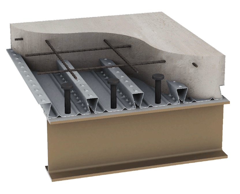
Headed shear studs can be directly welded, or through-deck welded, to the steel beam flange after the decking has been installed. Transmit the horizontal shear force between the concrete and beam connection and are commonly used in the design and construction of composite beams.
~95/100mm and ~120/125mm are the most typical options for use with SMD products. Other sizes are available.
• Shear studs manufactured in accordance with BS EN ISO 13918:2008
• Yield Strength – 350N/mm2 (minimum)
• Tensile Strength – 450N/mm2 (minimum)
• Elongation – 15% (minimum)
| Product Type | Product Application | Dimension a | Dimension b | Fixing Of Product |
|---|---|---|---|---|
| Welded Shear Stud | Through-deck Welded | 95mm (LAW) | 19mm | Ferrules Req’d |
| Welded Shear Stud | Through-deck Welded | 120mm (LAW) | 19mm | Ferrules Req’d |